• TalkBass has been independent since 1998. Add your voice.
    Create a free account to reply to discussions, view embedded media, and browse with fewer display ads.
    Join freeLog in
    Want zero display ads or expanded classifieds tools? Compare plans.

A short scale acoustic bass guitar experiment.

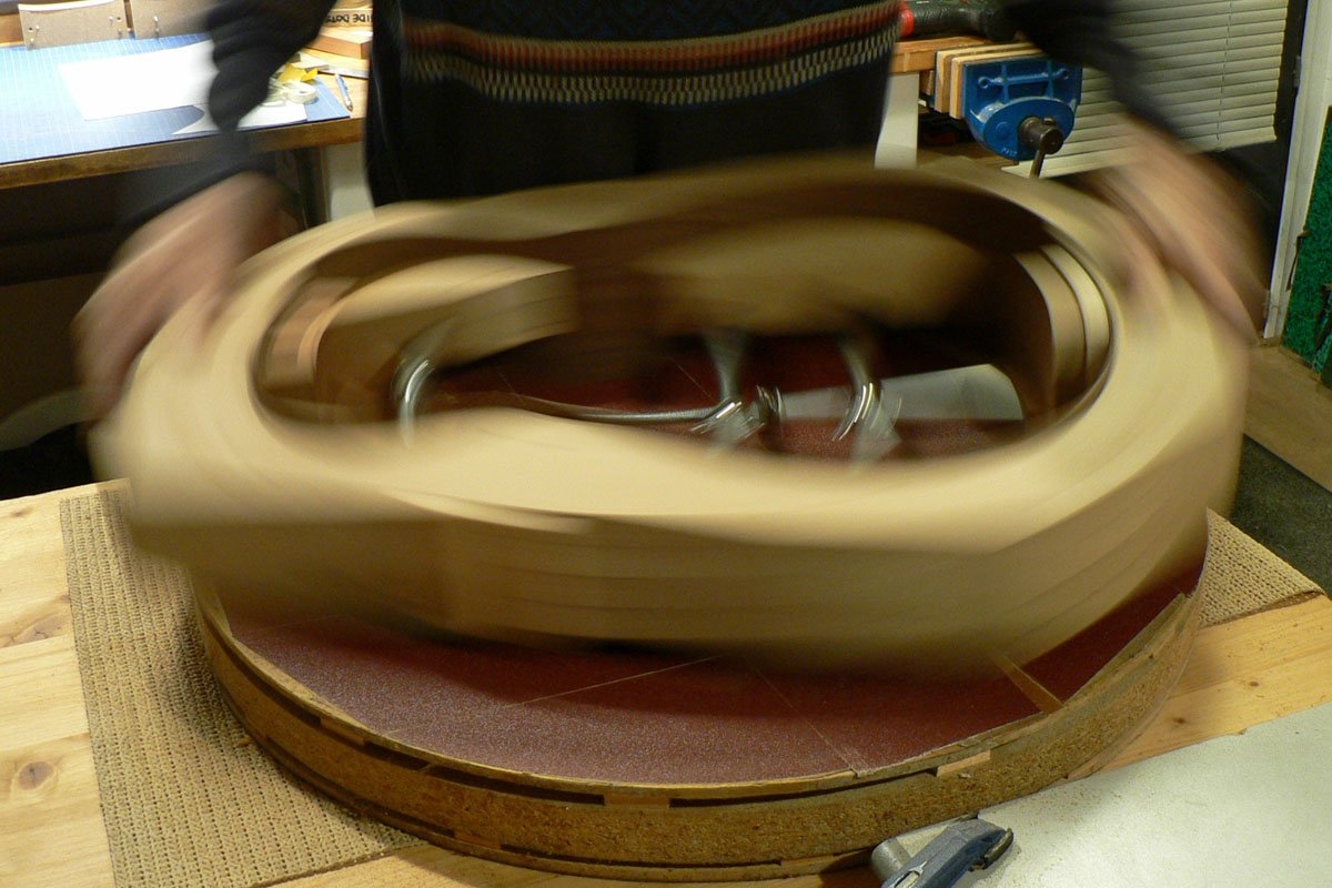
'Driving the bus'. The surfaces of the neck and tail blocks and the sides all need to be sanded to a spherical surface with a 15 ft radius. This is done in the radius dish with cloth backed abrasive stuck to the surface

Body 040.JPG


I forgot to take a photo, but I chalk all the surfaces that will need to be in contact with the back, and then sand until the chalk's all gone. It's quite strenuous, specially at my age, and especially when you realise that the sides aren't sticking out of the mould far enough and you're sanding the mould as well. But I got there in the end.

Body 041.JPG


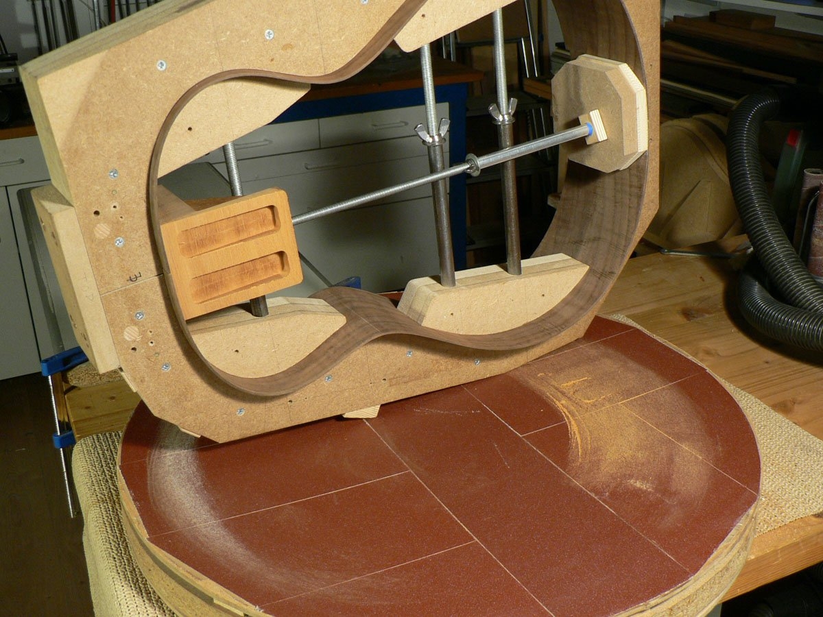
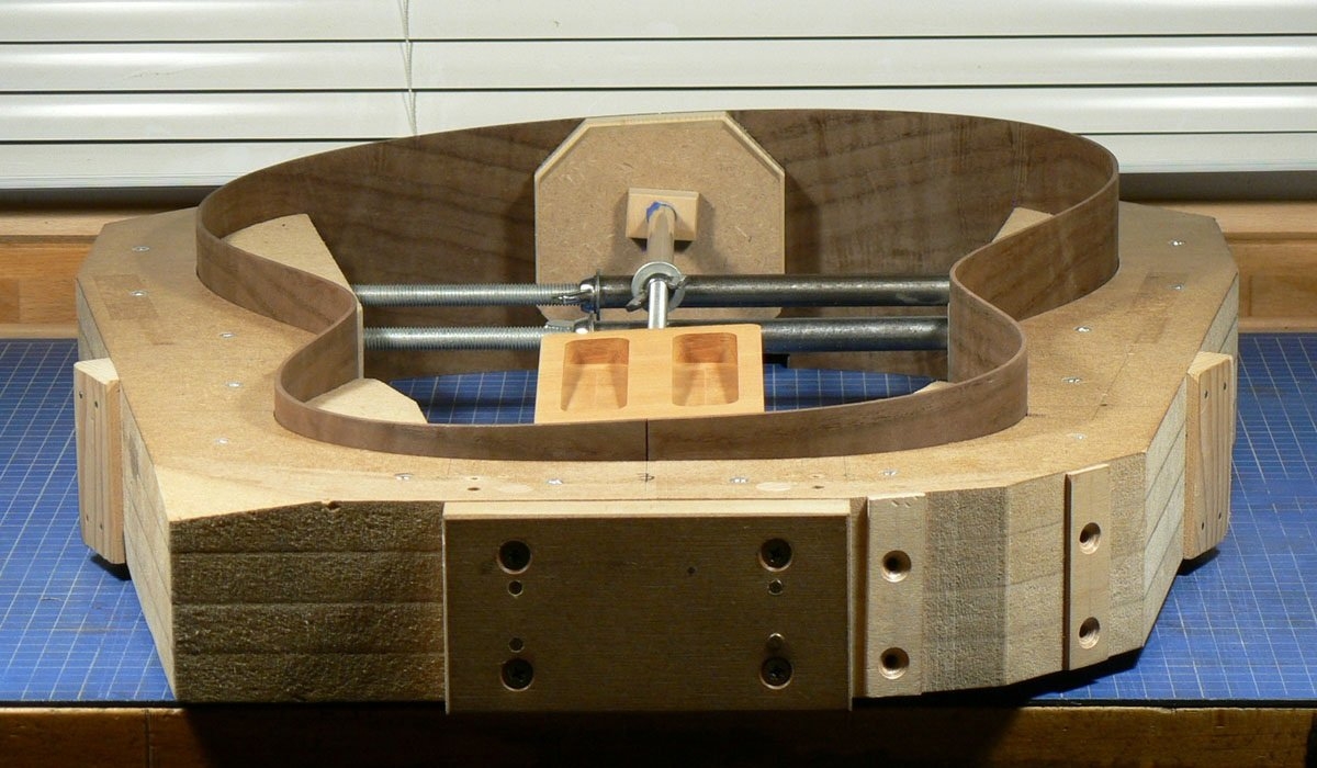
Now you can see the peculiar shape of a 'wedge' body.

Body 042.JPG
 
The force exerted by the strings tries to pull the neck forward and the neck on old and valuable guitars was almost always glued into the block inside the body. This could result in the body deforming slightly and the neck tilting forwards needing a neck-reset, a difficult, delicate and expensive job.

Modern guitars often have bolt-on necks but this can still be a problem, so some luthiers incorporate struts between the front of the neck block and the sides near the waist to try to minimise the possibility of distortion.

Two pieces of wood (which I call buttresses) are glued to the sides at the waist but first I need to drill holes in them for the struts.

Body 043.JPG


The gluing surfaces are sanded to match the curve of the sides in the same way as the neck and tail block, but this time with the sandpaper on the actual sides.

Body 044.JPG


The chalk's almost gone, so I'm nearly there.

Body 045.JPG
 
Amazing work, this definitely isn't your first rodeo, is it? Please tell me it's not.

I am a bit intrigued as to why/how you choose the position of the buttresses behind the waist of the body. Is it too hard to get them ahead of the waist, or would that create too much lateral force because of the higher angle? I have no doubt the glue joint is more than strong enough for the forces at play, but I still don't love a glue joint working in tension/shear like that.
 
  • Like
Reactions: Matt Liebenau
Amazing work, this definitely isn't your first rodeo, is it? Please tell me it's not.
No,I've done this several times now. I learnt from several professional luthiers via forums, etc. and the position of the buttresses was decided more by intuition than engineering. It's true that the force on the glue joint between buttresses and sides is in shear, but it's a relatively big area and the buttresses will also be notched into the linings as you'll hopefully see later.
 
As has been mentioned. Smaller and less resonant basses will tend to be more feedback resistant. I have a Tacoma Thunderchief, which has a fairly large body and a very light build, as I believe it was designed to be as loud as possible acoustically. I actually sounds fabulous amplified, but gain before feedback is pretty limited.

My Thunderchief has the Fishman preamp like this:
1767910316205.png

By fiddling with the controls I can get a decent sound at what I consider moderate volume. I have done gigs with a drummer with no problems. However, the drummer was not bashing the kit.

I would start by flipping the phase control a few times. This control flips the polarity of the bass's output. The best position depend on the polarity of the amp and how far the bass is from the speaker. As has been said, the phase switch doesn't really fix the problem, but it can move the problem so it doesn't overlap with another problem. Also, it may improve the sound in one way and make it worse in another. Listen to how it changes the sound and choose the best compromise.

Next I would turn up the bass till it starts feeding back. Align the notch filter with the feedback frequency and then turn the bass back down to a normal level. I don't understand why more notch filters are not built into preamps. In my experience, you don't hit the point of diminishing returns until you have applied anywhere from 4-6 notches.

Lastly fiddle with the Contour and Frequency controls. These controls are basically a variable frequency mid control. Most likely you will use them to apply a gentle cut to suppress feedback. As with the polarity control, you may find that Contour improves the sound in one way and makes it worse in another, so choose whichever compromise suits you best.

You may have to try a couple a times before you get a usable sound.

Since distance between the guitar and various sounds sources is a factor, consider changing location and moving your amp.

Another thing that can be helpful is a sound hole plug. I used to work with someone who played a nice Martin in our country band. We found that a sound hole plug made a huge improvement over the amplified sound. Gain before feedback was higher and the tone was better.
 
Hi Dave, I'm having a senior moment.

Are the rods going from the top of the neck block to the bottom of the side, and hence under compression. Or the bottom of the block to the top of the sides, and in tension?

I haven't done flying supports yet, though had pencilled them in for my next build, and got as far as drawing them out. I had them in compression, from the top of the neck block to the top sides.....


Are the rods going from the top of the neck block to the bottom of the side, and hence under compression. Or the bottom of the block to the top of the sides, and in tension?

I haven't done flying supports yet, though had pencilled them in for my next build, and got as far as drawing them out. I had them in compression, from the top of the neck block to the top sides.....
You had them the right way John. Near the front at the neckblock and near the back at the waist so they are in compression.
 
Last edited:
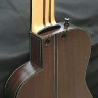
Whatever this thing sounds like, it's going to need amplifying if I want to play it in a band so I have to make provision for a jack socket. On other instruments I've incorporated the socket into the access panel and the nut that holds the socket in place also holds the access panel, but it's not a very satisfactory arrangement. So this time I'm going to put the socket a bit further round the side and that area will need reinforcing. So here's a piece of wood (Spanish cedar) being glued in place to do just that.

Body 048.JPG


I drilled the hole for the socket before gluing the reinforcement in place. I'll drill through the side later.

Body 049.JPG
 
I now need some linings. As the sides are a peculiar shape I would perhaps get away with straight linings for the front, but straight linings on the back would finish up varying between about 1/8" and 3/4" deep. So I make linings to match the profiles of the sides. I start by kerfing the strips of wood on the band-saw.

Body 050.JPG


I make the first saw cut, move the wood over so the kerf is located on the pin and cut another one, etc., etc.

Body 051.JPG


Once the linings are trimmed to size, this is what they look like. The two at the top are for the front. They are the same shape but right and left-handed. You can see what turning the back at an angle does to the shape of the other two.

Body 052.JPG
 
Gluing the first lining in place. Most people used to make linings with a triangular section and glue the smooth surface to the sides and some luthiers still do. Then someone had the idea of making them a rectangular section and gluing the kerfed surface to the sides. This makes the sides much stiffer which is thought by many to be 'a good thing'. So that's what I do.

Body 053.JPG


I also reinforce the sides even more by gluing a couple of strips of veneer to the linings as you can see here. There's also an extra piece of lining glued to the front lower bout which will have an arm bevel (if I don't cock it up).

Body 054.JPG


This was quite time consuming and a bit tricky as, although it's not easy to see in these photos, the linings are notched around the buttresses and the jack socket block, making them an integral part of the whole side assembly rather than just being 'glued on'.

Body 055.JPG
 
Dave sorry for the derail...... I'm stubbonly refusing to go down the CNC route, but would love to have a milling machine for more precise parts, blocks etc. What do you use?
It's a small bench-top model John, identical to this one. It's Chinese and dealers import it and stick their own name on it. It's not very powerful but I use it mostly for machining wooden components, occasionally brass or aluminium.
Invalid Link Removed
 
It's a small bench-top model John, identical to this one. It's Chinese and dealers import it and stick their own name on it. It's not very powerful but I use it mostly for machining wooden components, occasionally brass or aluminium.
Invalid Link Removed
OK, I'll add that to the (not inconsiderable) tool wish-list....
 
Sorry to bang on about the flying buttresses, and probably this is ridiculous, but did you glue them in relaxed, or pre-stressed (them that is, not you....)? I can see reasons for doing it both ways. Relaxed means that as the strings apply torque, the force is taken up by the top, back and buttresses equally. By pre-stressing, could you persuade more of the torque to be taken up be the buttresses and sides, freeing the top to vibrate more?

As you can probably sense, from an engineering point of view, I'm way out of my league here!:)
 
  • Like
Reactions: NKBassman
Sorry to bang on about the flying buttresses, and probably this is ridiculous, but did you glue them in relaxed, or pre-stressed (them that is, not you....)? I can see reasons for doing it both ways. Relaxed means that as the strings apply torque, the force is taken up by the top, back and buttresses equally. By pre-stressing, could you persuade more of the torque to be taken up be the buttresses and sides, freeing the top to vibrate more?

As you can probably sense, from an engineering point of view, I'm way out of my league here!:)
No, they weren't pre-stressed. The only thing slightly stressed was me. Trying to glue both ends of the strut and the buttress to the side without getting epoxy everywhere tends to make me grit my teeth a bit. :)
 
I now need to make the access panel. I make the panel first and then cut the hole to fit. It starts with some more off-cuts.

Body 059.jpg


Two pieces of spruce glued together and a disc cut out. The sapele is glued to another piece of spruce and two circular segments are cut out. A piece of the flamed maple is glued to another bit of spruce and trimmed to a wedge shaped end graft and four bits of black and white veneer are cut.

Body 060.JPG


The spruce disc is sanded to its finished diameter.

Body 061.JPG


The black and white veneers are glued to the wedge.

Body 062.JPG


Now the wedge is mounted on the spruce disc, but not glued, and held in place by the two small spring clamps. The two semi- circular parts are glued to the spruce disc. The central clamp holds them in close contact with the wedge and the four large clamps apply pressure.

Body 063.JPG


Body 064.JPG
 
I now trim this part of the panel to the required diameter.

Body 065.JPG


The panel needs a white veneer to be glued to it and, although the veneer would easily bend round it, it's much easier to glue on if it's already bent. It doesn't need to be exactly the same radius. I've already talked about this 'bending iron'. It's a steel tube with a 200w (I think) halogen bulb inside and the bottom of a Coca-Cola tin wedged in the top.

Body 066.JPG


The veneer is taped in place slightly proud of the surface of the sapele which makes it easier to apply water-thin CA which wicks into the joint.

Body 067.JPG


The ends of the veneer are trimmed and the top surface sanded flush. I can't glue the wedge in place yet, as the next job is cutting the hole for the access panel and I need the panel, without the wedge, to check the size of the hole.

Body 068.JPG