• TalkBass has been independent since 1998. Add your voice.
    Create a free account to reply to discussions, view embedded media, and browse with fewer display ads.
    Join freeLog in
    Want zero display ads or expanded classifieds tools? Compare plans.

Any DIY pedal builders on TB? Strut your stuff!

after reading the praises in another thread of the JPTR Jive, i did some research and found out that its a Zvex SHO with three clipping diode modes (on the output) plus a master volume out. i was going to buy one to try it out but since it's such a simple circuit i decide to build one for myself in a 1590B with all top jacks in an acid etched enclosure. Besides it costing me much less, the other advantage is that i built it in one day and didn't have to wait for one to arrive. (just an FYI, since it looks almost exactly like the original,i have no intention of selling it)
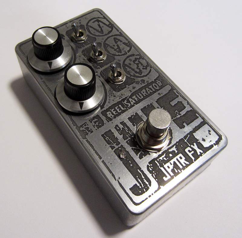
Jive-001.jpg
 
Last edited:
20220801_145458_small.jpg


Got a PCB for the MadBean Flunkee in the December 2019 giveaway and decided to toss it together. the 1590A-sized board was surprisingly a bit of an awkward fit in the 1590B enclosure but I made it work (albeit not nicely). Wasn't going to do anything fancy for the enclosure decorations but ended up going a little ham with the paint markers for the result you see above. Pretty good filter but I'm not finding the BP mode useful and I find it doesn't respond as quick as I'd like (pretty much only find it useful with the sensitivity at minimum). Not complaining too much for a free PCB though!
 
What are the grunt/attack mods done to the VMT?
The Aion circuit board is intended for the B3K, but can be built as a VMT with a couple component substitutions.
So it's the same grunt/attack functionality that's found on the B3K.

Here's the build documentation:
Maelstrom Bass Drive - Aion FX
 
Ten more FuzzDog projects arrived from overseas. Had to justify s&h expenses by buying more! Half of these circuits I've built before on stripboard or in larger enclosures. This haul will keep me busy for the next few months.
Top row: Expandotron ZZ, Echo Blue, Blue Fool.
Second row: Orange King, IC78 Muff, Mastodon.
1590A row: Tube Screamer, Bosstone, Vintage Soda.
Bottom center: Tone Bender mk.II w/voltage inverter.

20220803_174000.jpg
 
Added Tone Bypass and Mid Shift mods to my Bass Big Muff. These mods are easy to make; pcb doesn't need to be removed from the box and there's no need for desoldering or touching any SMD.
Toggle switch on the left is Mid Shift. It's a SPDT On/Off/On. Pin 1 goes to 5.6nF cap. Pin 3 goes to 15nF cap. The other ends of both caps are twisted together and wired to TONE_3. Pin 2 of Mid Shift switch is wired to Q3 collector and a jumper also goes to pin 2 of the Tone Bypass switch. Switch in down position is flat response, switch up is mid boost and center position is stock mid scoop.
Toggle switch on the right is Tone Bypass. It's a SPDT On/On type. Pin 1 is wired to TONE_2. Pin 2 is jumped and wired to Q3 collector. Switch in up position is normal, switch in down position is tone bypass. This shorts out the tone section and bass boost section. Dry mode is still functional with tone bypass on.
Also swapped in a green LED and replaced the footswitch with a soft-click type with dress nut.

BassBigMuff_mods_top.jpg


BassBigMuff_mods_bottom.jpg
 
  • Like
Reactions: Fuzzonaut
I dont mind soldering smd by hand. Ive gotten a little better at it since this. The first board was to big so I ordered smaller ones. I learnes the hard way to turn the temp down on the iron, lol

View attachment 4760112


Here are the new ones for the open source pedals Matt:

JLCboards_firsttest.jpg


Took me right around two hours to stuff the two boards and that included ad libbing on parts values in a few places. It's a very easy build for those with SMD soldering experience now that I've gone back to through hole caps for everything.
 
Added Tone Bypass and Mid Shift mods to my Bass Big Muff. These mods are easy to make; pcb doesn't need to be removed from the box and there's no need for desoldering or touching any SMD.
Toggle switch on the left is Mid Shift. It's a SPDT On/Off/On. Pin 1 goes to 5.6nF cap. Pin 3 goes to 15nF cap. The other ends of both caps are twisted together and wired to TONE_3. Pin 2 of Mid Shift switch is wired to Q3 collector and a jumper also goes to pin 2 of the Tone Bypass switch. Switch in down position is flat response, switch up is mid boost and center position is stock mid scoop.
Toggle switch on the right is Tone Bypass. It's a SPDT On/On type. Pin 1 is wired to TONE_2. Pin 2 is jumped and wired to Q3 collector. Switch in up position is normal, switch in down position is tone bypass. This shorts out the tone section and bass boost section. Dry mode is still functional with tone bypass on.
Also swapped in a green LED and replaced the footswitch with a soft-click type with dress nut.

View attachment 4771402

View attachment 4771403

Do you like the Tone Bypass option? I put it on a madbean muff and just don't think it's that useful... would love to hear someone talk about how it "is" useful to them. Maybe I'm not using/thinking about it the right way.
 
Do you like the Tone Bypass option? I put it on a madbean muff and just don't think it's that useful... would love to hear someone talk about how it "is" useful to them. Maybe I'm not using/thinking about it the right way.
I'll get back to you after I've had more time to try it out yet. First impressions yesterday were that it sounded better at lower gain settings than high gain settings.
 
I'll get back to you after I've had more time to try it out yet. First impressions yesterday were that it sounded better at lower gain settings than high gain settings.

I just felt like too much bottom end dropped out and it accentuated the high end too much.

Lately I'm also finding that muff's sound way better with the tone around 1 o'clock and the sustain around 3 o'clock. Overall, it sounds a lot better and fuller when it's louder... but the downside is that it's too loud.
 
Here are the new ones for the open source pedals Matt:

View attachment 4771493


Took me right around two hours to stuff the two boards and that included ad libbing on parts values in a few places. It's a very easy build for those with SMD soldering experience now that I've gone back to through hole caps for everything.
Very nice. Doesn’t look to bad. Well done.
 
  • Like
Reactions: Passinwind
I believe this enclosure configuration was suggested / requested on the original Rails thread. It sounded like a pretty good idea and I thought I would give it a shot. Circuit Design by Frank Appleton and JoknK. That was a great collaboration. I had my own pcbs made. This one has the V1 boost section as opposed to the later V5 . Relay bypass footswitch. Boost switch on a toggle with a green led indicator for on. 125b with top jacks. I’m pretty happy with the way it turned out and it sounds great. Thanks Frank and John.
Matt.
161DA435-27D4-4682-A4FF-F656BE645933.jpeg
 
I believe this enclosure configuration was suggested / requested on the original Rails thread. It sounded like a pretty good idea and I thought I would give it a shot. Circuit Design by Frank Appleton and JoknK. That was a great collaboration. I had my own pcbs made. This one has the V1 boost section as opposed to the later V5 . Relay bypass footswitch. Boost switch on a toggle with a green led indicator for on. 125b with top jacks. I’m pretty happy with the way it turned out and it sounds great. Thanks Frank and John.
Matt.
View attachment 4771967
Very nice. Is it just the boost section or ?

I've been on the fence between building something, buying a Master Effects Super 800, and just buying a GK. I dont need a GK...