• TalkBass has been independent since 1998. Add your voice.
    Create a free account to reply to discussions, view embedded media, and browse with fewer display ads.
    Join freeLog in
    Want zero display ads or expanded classifieds tools? Compare plans.

Building: Tools, Fixtures, Jigs & Templates

If the proof is in the pudding ...
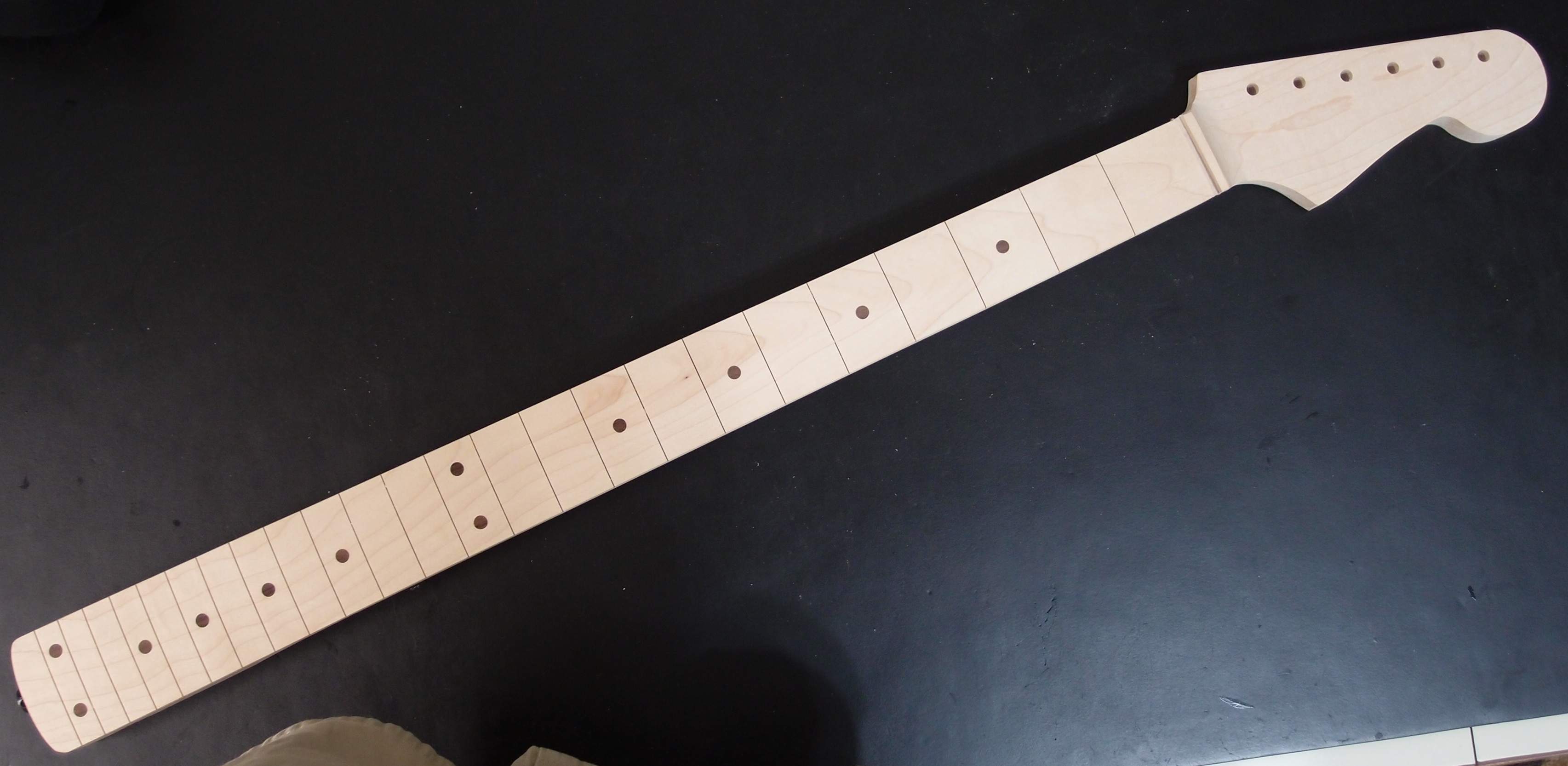
PA080787.JPG


... then dessert is served. Here is one of several projects that I have running concurrently, a Bass VI neck. It is not finished, but far enough along to show. The back is maple from Home Depot, about eight dollars worth. The fingerboard is from Lowes, another two bucks. It's just a plain piece, but a nice grain pattern, I think.

As I said earlier, here in the Northeast, the maple in the hardware stores is the good kind. In California that would probably not be the case. You can check by determining the density of the piece - if it is 44lbs/cu-ft or thereabouts, it is the good stuff, less and it is not. Bring a scale, calculator, and rule to the store and you can determine it right there.

Of course, when you're out wood-shopping make sure you pick through the whole pile for the best piece - straight and pretty, even figured, some of it may even be accidentally quartersawn, although I don't believe that makes a difference. One thing to remember about figured wood is that all the pretty figuring is actually all flaws in the wood. For example, run your fingers over a flamed piece, and you can feel the ripples. That will make it weaker than a plain piece, and can also make it harder to work and finish. Birdseyes are actually all tiny knots as near as I can tell, and spalting is literally rot. I also try to avoid pieces with really asymmetrical grain patterns when looked at end-on, but I don't really know why, realistically, it doesn't seem to matter.

The dots in this neck are rosewood plugs cut from scrap, but could just as easily be walnut from the hobby store around the corner, five bucks would buy a lifetime supply. Side markers will be cut from 3/32" plastic rods, again available from the hobby shop, or use anything you have that is about that size. A neat idea I read is to use those little red straws that come with canned-air & Wd40. Fill the center with white spackle for a red bulls-eye. Glow-in-the-dark material is available on eBay, I may get some for later. I was toying with the idea of using bits of brass rod, but that might be hard to work. I think Danelectro used tiny nails, and ground them flush. For now I will use black plastic material available very inexpensively from StewMac.

So far, hardly any "luthier" materials, but if I had sourced it all that way, the total would be well over 50 bucks just for the wood. And it really wouldn't be any better. In fact, I would rather hand-pick my pieces at the hardware store than mail-order them sight-unseen for ten times the price. "Luthier" neck blanks tend to be a bit thicker than the 3/4" stock that is readily available. Makes no difference, especially if you are adding a 1/4" thick fingerboard to the top. In fact, it could end up being more work grinding away the extra thickness you don't want.

I just picked up a 1/4" piece of walnut from the hobby store to see how it will work. I also have some 1/4" red oak that I have an interesting plan for. Red oak is highly reactive to water and iron, it stains indelibly black. If you make a solution of fine steel wool dissolved in hot white vinegar and soak the wood in it, should blacken the entire piece right through. Seems like it should work, and oak is about as hard as maple, for a fingerboard.

For neck backs, I have also used poplar. Danelectro made literally millions of necks from poplar. Poplar is noticeably weaker and softer than maple, which makes it easier to work, but requires some changes in design, larger radiuses on transitions, thicker headstocks, etc. It finishes very nicely as well.

Oak is pretty much equal to maple in strength and hardness, but has an open grain structure that would require a lot of filling, and also is not uniformly hard over the entire grain, which means the more you sand it, the more uneven it becomes. This could be overcome by scraping instead of sanding, but oak is of no interest to me for this application. In fact, that might rule it out for a fingerboard as well. Likewise, I have no interest in mahogany, which is as awful to finish as oak, and weaker even than poplar.

One wood that I do plan to try some day is southern yellow pine, and also the 'radiata' pine that has become so common lately. The specs for both are actually somewhat better than 'hardwood' poplar, and it is very easy to work and finish. Suitable pieces with clear straight grain are readily available. With proper steel support and a hardwood fingerboard, I don't see why these woods wouldn't make excellent necks. White pine, on the other hand, looks like a pretty poor choice for a neck, so weak and soft, although I think you could make a nice easy body of it.

That pretty much covers all the woods that are readily available without resorting to 'luthier supply'. However, if you're not into experimenting, then just stick with hard maple for necks, you can't go wrong.

I added a detailed description of the truss rod where promised in a previous post. There are more pictures there.
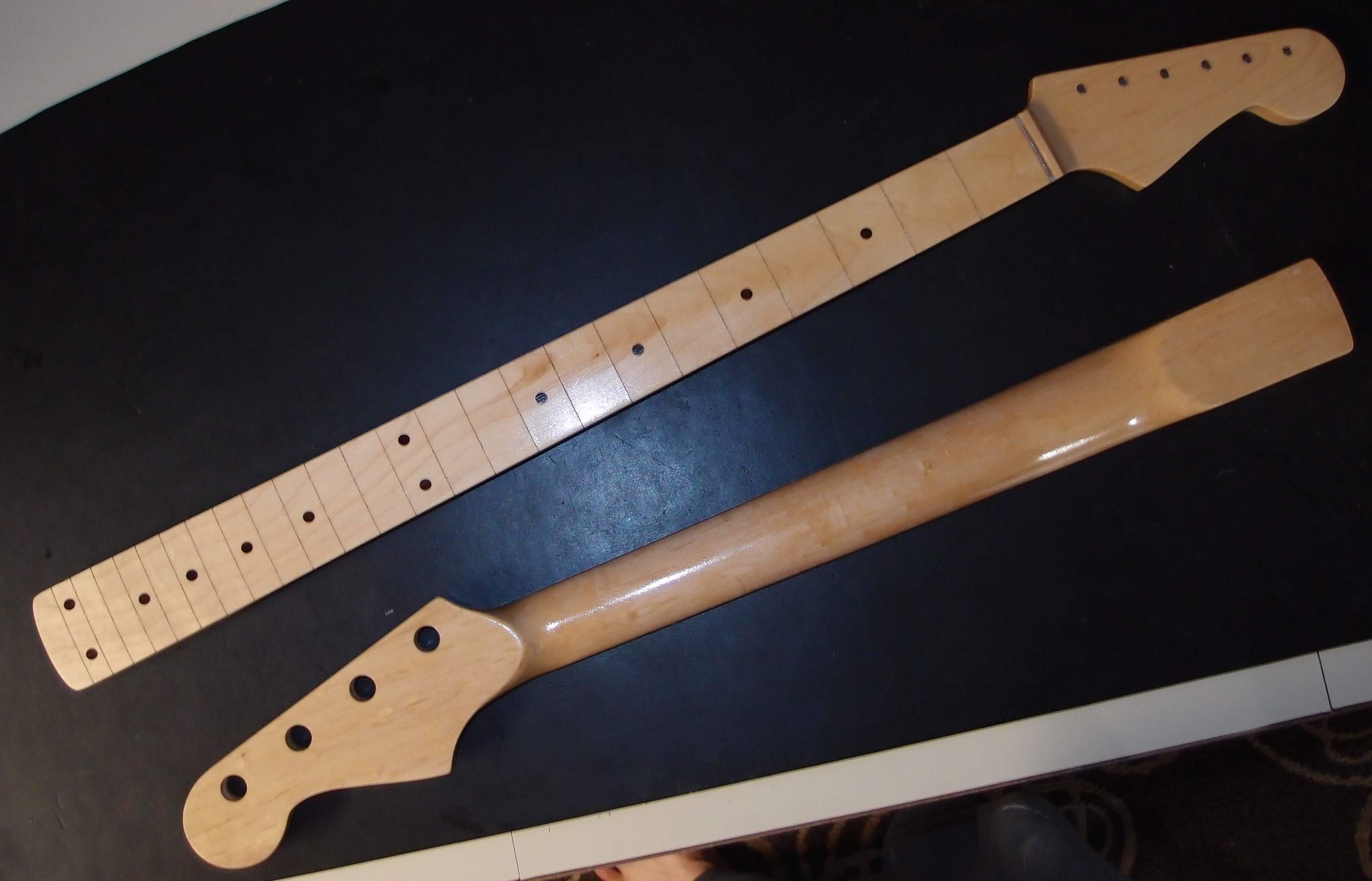
PA110795.JPG

The same neck after some Minwax "Natural" stain and several coats of wiped-on poly. Notice how the stain has warmed-up the white maple. The other neck is an Eden paddle-head Strat. This is my only experience with Eden, and I'd say that this individual neck is a good piece.

See the finished guitar here.
 
Last edited:
Here's a freebie nut spacing rule I made some time ago. Just print it out on a piece of paper, and fold over on the center line. Don't worry about the printer scaling, it doesn't matter. To use the rule for a guitar, mark the two E strings on the nut and slide the rule until the marks line up with 4 between them. Et cetera.

nut-spacing.gif


Each tick mark is about 5% wider than the previous one, something like that, I don't remember. That means each long mark is 10% bigger than the previous one. So if you use only the long marks, you get one scale, and if you use both the long and short marks, you get another scale. Knock yourself out. While this works in theory, in practice it is easier to just buy a pre-slotted nut and keep it for a template to copy. The rule is big enough to do bridge spacing as well.

Nut making is something of an art. There are lots of expensive gauged saws and files on the market for cutting string slots. You don't really need them. A razor saw will cut approximately 0.010" slot. The fret slotting saw will cut approximately 0.020". You can work it around to make 0.030". For slots bigger than that, you can resort to needle files from the hardware store.

Also useful are welding tip cleaners, which are often sold on eBay as fret files, and work well in softer materials and even aluminum, although they don't last long in anything other than plastic. Cheap "fret file" sets from China are useless junk - save your money. Real ones come from Japan, and are expensive.

Most of the time I just get pre-cut nuts and tweak them, rather than do the whole thing from scratch. The exception is if I want a brass nut, which are expensive and hard to find. I make those from brass bar stock. A dremel with a fine cutting wheel can also be useful, but you have to be very careful not to over-cut. Aluminum is an often-overlooked material for nuts, but is not suited for tremolos as it tends to bind.

Brass nuts are prone to buzzing if you get the bottom angle of the slots wrong. Softer materials are less likely to have this problem. Like I said, it's an art, and you're probably better off just buying it.
 
Last edited:
Carving Necks & Bodies - Indispensable Tool

For making both becks and bodies, this oscillating spindle / belt sander from Home Depot is indispensable.

The belt attachment is what makes it far superior to an ordinary spindle sander. Belts have a far greater working area than the small cylinders most spindle sanders have. They last longer and are cheaper to replace, and are available in a wider varienty of grits. The #36 belt is ideal for removing material to make a rough shape, then clean up with a #80. The big end of the belt drive is a 2-1/2" diameter, which turns out to be by far the most useful part of the machine, and exactly matches many of the curves on a Fender neck. Of course, there are smaller spindles all the way down to 1/2" for tight spots. The flat on the belt will cut reasonably straight for small parts that fit entirely in it, but anything that overhangs the ends is going to be gouged by the rollers unless you are very careful - light touch and always moving the workpiece. It's good exercise.

To make a neck, draw it out on a wood blank, and route the truss rod channel. If the channel comes out a little off-center, redraw the neck around it, then cut around the drawing with a bandsaw. Clean up by sanding square to almost the outline, but do not sand all the way to your marks, especially not with the 36 belts, as it leaves deep gouges that will have to be sanded-out later. Now glue on the fingerboard, then trim and smooth it to match the back. Sketch the contours of the transitions at the back of the heel and headstock, and then bandsaw away part of the back corners in-between. Return to the sander with the 36 belt installed, and start contouring the back. At this point, you are just trying to rough out the curve, stay away from the sides of the fingerboard or your neck will come out too skinny.

This is the tricky part. You'll simply have to develop a feel for how to do it, so practice on a lot of scrap. Do not simply press the piece against the belt and hold it - that will never come out even. In fact, I use the rounded end a lot more than the flat. Use a light touch, and always keep the piece moving, flying really. Anywhere you stop is going to cut a valley. The hardest spots to get even are the ends near the head and heel. I cut those first, shaping on the round end with the table dropped, using all kinds of crazy angles to make the right contours. Then sand the rest of the neck to match, and finally carefully use the flat to even everything out.

There is simply no way to adequately describe this process in writing, it just takes practice. Buy yourself some cheap maple to practice on, lay out some fake necks, and plan to make a lot of ruined scrap before attempting your first real neck. Ruining that would mean having to start over, with the loss of all the work you've already done on the fingerboard and other profiles. Soft pine is also a good practice wood, it is cheap and you really have to learn to be careful as it cuts so fast.

Remember, you are not going for the final profile with the 36 belt - that would not leave enough material to smooth out the tooth marks. Once you have the profile roughed-out, smooth it down a bit with an 80 belt, and then it is time for hand tools. For making straight sides on the fingerboard, use a mill bastard file ( the kind with big teeth. ) Grind any burr off the handle of the file first to avoid scratching, then use the full length of the file lengthwise against the wood. It is a slow process, but that assures you don't over-cut, and the result will be dead straight, you'll be amazed that you did that. You can also use the file to level any remaining bulges in the back of the neck the same way. Japanese flat-cut rasps are also ideal for this, but they are expensive, and a mill bastard file from the hardware store will get the job done. Another thing you can use is a small powered palm sander, but be aware that this will leave tiny swirl marks in the wood that will have to be sanded out by hand. Wood scrapers are also very useful for final contouring. StewMac has nice ones. You could also use a sanding block.

When you're happy with the back, it is time to thin down the headstock. That was described in a previous post. Drill the tuner holes first from the back, so that any tear-out from drilling will be removed in this step. The curved ramp from the fingerboard down to the headstock can be shaped free-hand on the spindle sander using a 3/4" drum. Again - tricky, practice all operations on scrap first.

Finally, you must fit the heel to the body. Hopefully, at this point the neck heel is just a little too fat to fit in the pocket. Using the flat on the belt sander and a fine belt, carefully work down the heel until it makes a snug fit, and then just a tiny bit more to allow for the thickness of the finish. Re-straighten the sides with the file if necessary.

There is no magic neck contour. Fender has C-shapes, and D-shapes, and U-shapes, and V-shapes, and W-shapes, in fat and skinny, and it all really makes very little difference. If you put your thumb on the back of the neck, you're gripping a lot more air than wood - go try it right now. As long as it feels good to you, that's right. I concentrate much more on getting the neck smooth and straight, so as you run your hand down it, you don't feel any hills and valleys along the length. What you definitely don't want to do is sand right through to the truss rod channel, or make a neck that is so thin that the truss rod breaks out the back. I like a slightly chunky neck, and the extra wood makes it much much more stable than a skinny neck. I usually go for a cursive-Q neck profile, or sometimes a lowercase h.

So - go slow, light touch, keep moving. All this is hardly adequate instruction for what is really an art that can only be developed by practice. The best advice I can give you is to turn a lot of perfectly good wood into sawdust and scrap before attempting a real neck. Do not go for your final profile too soon, ideally, you will reach your final dimensions as you are doing your final finish sanding. That is something that comes with experience. If you end up throwing away your first neck, don't feel bad. But your second or third one will be something you can be proud of. Rest assured, if you put in the time and effort, you can learn to build your own necks as good as anything you can buy, if not better.

For doing bodies on this machine, first bandsaw the rough outline. Outside curves are easily done against the flat of the belt. For inside curves, always us the largest diameter spindle that will fit. All the advice above for necks applies to bodies as well. For tummy and arm cuts like a Strat, sketch the outline on all faces, drop the table on the sander, and free-hand it against the fat roller of the belt. It's not as scary as it sounds. Finish up with a palm sander. It is usually better to route the neck pocket first, so that the router has the entire slab of wood for support.

Always wear a dust mask when sanding. This machine can quickly turn a lot of wood into a lot of fine airborne sawdust that you absolutely do not want to breathe in. Even when hand sanding, the dust will be right in your face - wear a mask. Many of the tropical hardwoods used for fingerboards make highly irritating dust. You can end up hacking your lungs out for weeks. Wear a mask.
 
Last edited:
No-drill Jazz Bass Thumbrest

PA090790.JPG

Yes, it's a Geddy​

Here's a project anyone can tackle. Maple scrap, shaped on the belt sander, but could be done entirely with hand tools and sandpaper. Goes on using existing holes and stainless steel screws from the hardware store. Completely reversible.
 
Last edited:
  • Like
Reactions: tzohn
A Note on StewMac and Tools

Stewart MacDonald ( Invalid Link Removed ) is a terrific resource for guitar parts and tools. But, hoo-boy, look at those prices ! Are they out of their minds? Well, no, not really. Here's why:

If look look at some wrenchy-looking thing at StewMac, and think, this is ten times the price of a similar wrenchy-looking thing at Home Depot, you must first remember that, for the most part, the two are NOT the same. StewMac's tool has probably been modified in some way for the very specific task of building a guitar. Or it may be manufactured from scratch for that purpose. For example, a fret puller looks an awful lot like an end-cutter. But Home Depot sells tens of thousands of end-cutters, while StewMac sells maybe a few hundred fret pullers a year. That is going to drive their production costs through the roof. So, even though their prices are high, they are not unreasonable, and the quality is always first-rate.

Another example is the radius sanding blocks. $16 seems like an awful lot for a small block of wood. But now you've seen just how much tooling it takes to make one, and how much labor, and the cost of materials, and all that cost has to be spread across relatively small production runs and inventoried and warehoused and shipped. There is no way I could make sanding blocks and sell them at their price, it would not be worth my time.

Sometimes it is possible to modify or duplicate their tools at a substantial savings. For example, my fret slotting jig. A simpler example, I purchased a small end-cutter at Sears, and ground the edge flush to make a fret puller. Sears also sells a nice cheap little plastic-faced hammer that is perfect for whacking frets, you don't need an expensive 'fret hammer'. Often, with a little creativity, you will find that you don't need a specialized tool, you can make due with what you have. But sometimes you just have to bite the bullet and buy the right tool, and StewMac probably has it. For example, their 'fret press' works far better than any hammer.

PA110791.JPG
Fret puller and its big brother fret cutter

ea2792eb-7e72-4708-9562-e859ffb04430_1000.jpg
An inexpensive bench grinder like this is a terrific investment. Apart from all the guitar-building uses I've mentioned, you can sharpen anything from knives to lawnmower blades, and find a hundred other uses for it.​

The same goes for their parts and materials. A StewMac fretboard is around $30 plus shipping, but consider all the work that went into it. You're paying for quality and convenience, and the price may be high, but it is fair. Generally, I will not make a part if I can buy it, for example, a standard long-scale bass neck. StewMac sells Mighty-Mite necks, which are as good as any, and for about $100 and a mouse click, I can have one any time I want. It is simply not worth it to make one, I only build the oddball stuff that you can't buy.

All the same arguments are true for AllParts. If you're like me, you can go bargain hunting on eBay.
 
Last edited:
Variations on a Theme

PA130796.JPG


Here is the Bass VI first test assembly, with tuners, but no nut, truss rod, or strings, along with the rest of the family.

Left to right:

Uke bass, 21.5" scale, with rubber strings, piezo bridge pickup, and active electronics.

SSB #1, 30.3" scale, PJ pickups, active electronics.

SSB #2, 30.3" scale, triple rail humbucker pickups, passive electronics, switchable pickup modes

Bass VI, 30.3" scale, stock pickups, passive electronics, passive distortion circuit, work in progress

Guitar, 1985 MIJ Squier Strat, modified pickup switching & illegal tremolo stabilizer

25.5" 'paddle' neck from Eden, cut & drilled for bass

The bodies are all Squiers. My policy is not to build things that can be reasonably bought. Look closely, and you can see which parts are custom-made, including, necks, pickguards, and other parts, and also how the stock bodies are modified. You can see four different solutions to the tremolo hole problem.

The maple and bubinga necks were made using the tooling described in this thread. The rosewood bass fingerboard is a shortened StewMac bass, while the uke is a shortened StewMac guitar.

Can't see it in this picture, but there is some gorgeous birdseye on the uke neck, from Home Depot. The uke tuners are modified for those fat rubber strings, and it uses a maple string nut. That build could be a thread in itself.
 
Last edited:
Airbrushing "off the grid"

Here's a little rig I made that let's me run the airbrush, or many other things for that matter, away from the compressor.

PA310812.JPG


On the left is my excellent Preval vFan airbrush that Home Depot gave me to evaluate. You can see the hose has a standard 1/4" male QD connector installed. On the right is a pressure regulator, with a standard female QD connector on the outlet side, and a scuba-to-NPT adapter on the inlet side. Plug that into an inflator hose on a scuba regulator, and set your output pressure on the inline regulator.

A scuba regulator outputs about 140 psi, roughly the same as a compressor, while the airbrush wants 20-40 psi. The flow rate is more than adequate to drive the airbrush, and breathing air is already super-clean, so no filter necessary. A typical scuba tank holds 80-100 cuft at around 3000 psi, and costs well under $10 to refill at the dive shop. The vFan spec is 5 cfm at 20 psi, which works out to over 15 minutes of continual spraying, or several hours under real conditions. This could even drive a bigger spray gun for a useful amount of time, but I don't think I will ever use it for anything but the airbrush, since Home Depot also gave me a nice compressor. It's like Christmas every month.

About $20 in parts. Of course, doesn't apply if you're not a scuba diver, or at least know someone you can borrow a setup from. I would like to note that this idea is not all that original, scuba-inflator tire chucks have been available for years, I just took it a little further. Preval also sells a compressed air product to power the airbrush, about the size of a hairspray can. It actually works pretty well, but would quickly get expensive to make much use of.
 
Last edited:
I like your opinions and thoughts- so much better when the reasoning is provided (altho it's just an opinion) as it gives basis to it all vs those that just make an unsubstantiated statement/opinion.
Great reading.

Mahogany is for boat decks and furniture, not guitar necks, it is too brittle.

Well, 'Mahogany' is for cabins, int and ext, while Teak is better for decks, rails, etc. Mahogany used for decks would be as bad as Mahogany alone (w/o volute) for necks, for different reasons.

whose favorite tone is the mush you get from a standard tone control?

...with old flats and foam? Each to their own...
 
  • Like
Reactions: divetone
Electronics Test Jig

1487693_68ba1b68cc1e4301d3c9526f0b6fdf54.JPG


This is a little test stand I built, along with some alligator clip jumpers from Radio Shack. It is a piece of aluminum angle attached to a piece of wood for stability. Different sized holes will take pots, switches and jacks, including even a blade switch. A 1/4" jack is installed permanently at each end. The aluminum angle automatically grounds everything.

In the picture, the input is at the right and the output is at the left, but this is entirely reversible. The red jumper is just connecting the hot leads. You can use anything for a signal source, I'm using a bass at the moment. Using the jumpers, it is possible to quickly assemble all sorts of configurations for testing, without soldering. You can also solder permanent assemblies and then remove them. One drawback is that any noise sources in the vicinity, such as fluorescent lights, are picked up very strongly.
 
Here's another quick jig:

P5080909.JPG

I guess I would call this a finishing stand. It is vaguely inspired by StewMac's typically over-designed finishing stand. I think mine is more practical, and does not require a bench vise, which means you can use it anywhere. It is also $90 cheaper. Credit where credit is due: many of my ideas come from flipping through the StewMac catalog, although I think I often improve on their designs, and definitely improve on their prices.

What you've got here is an open frame made from scrap 3/4" plywood that I think I found somewhere, fast and free. I just cut the pieces freehand and liberally glued them together - no fasteners - I let the tackiness of the glue hold it all together until it set. You can just see the two triangles of scrap wood that brace the uprights. I came back two days later, and it was solid as a rock. I quickly broke over all the edges with a sander and then sealed them with poly as I worked on the real project, because plywood splinters are not my favorite thing in the world. The distance between the uprights is 22" - enough to fit a jazz bass body. The height is whatever took the least amount of cutting with the circular saw - the whole thing was together in literally minutes.

You can see a long thin screw in the strap button hole, and a handle attached in the neck pocket. The handle is a scrap of 1x2, drilled to match the neck mounting holes in the body and attached with 2 drywall screws, with a coat-hanger hook at the other end. Thus, the attachment points are places that will be hidden in the finished product. The handle allows you to 'clock' the workpiece at 90 degree angles for finishing. Here. I'm using some triple-thick brush-on polyurethane that Home Depot gave me to evaluate. The stand would work equally well for spray applications, and allows access to all sides and edges at once.

The goal with this piece is to build up a thick layer of plastic as quickly as possible, and brushing beats spraying, and all you need is a brush - not a whole spraying setup. I let each coat get just dry enough to touch, and then add another, so they all bond together into a single layer. You don't get a smooth finish like this, that comes later after wet-sanding and polishing. Prior to this the ash body was grain-filled and sanded smooth, and given three coats of 'natural' stain, which gives that nice aged yellow color, as opposed to the white you can see inside the cavities.

So far, everything is working perfectly, and much easier than the old Fender trick of balancing the body on three long nails in the pickguard holes, or clamping the handle in a vise.
 
Last edited:
  • Like
Reactions: JustForSport
P5150948.JPG


This is my best truss rod design, and the end of my truss rod evolution. This truss rod adjusts at the heel with a MusicMan-style spoke nut ( $5 from StewMac ) although you could use whatever nut you like. The result is the strongest possible neck that is easy to adjust without removing the neck or needing any special tools. I use an old drill bit for a lever.

Also, the rotating assembly is kept as compact as possible, and the required thread-cutting is reduced to an absolute minimum by using a store-bought bolt as the core for the adjusting mechanism.

This design places all the bulky components in the neck heel, where there is plenty of room, as opposed to the headstock-end, where the neck is thinnest. One of the reasons so many Gibson necks break is their insistence on hollowing out the smallest part of the neck to fit in the truss rod adjusting mechanism.

The top end of this rod is as compact as it possibly could be. The rod is installed only after the neck is completed, as the protruding spoke nut head would interfere with finishing. Normal tension locks it in place, but it can be removed at any time by simply slacking it. This is a double-acting rod, it can push or pull, one of the only ones that can use a spoke nut.

In the photo, the rod is upside-down. At the bottom is a piece of steel bar stock. Above that is a piece of steel rod. The two are brazed together at the other end. Alternately, you could bend a double-length piece of round rod back on itself, the bend taking the place of the far braze joint. I've made them that way too. The big advantage to doing it that way is that the round rod is cheaper and more readily available than the rectangular bar. Finally, you could also use 2 single-length pieces of rod and braze them together in place of the bend, but I think keeping the round pieces aligned would be tricky, and I have never tried it. None of this makes any difference in the function of the finished product.

A properly-made silver braze joint is actually stronger than a weld, so don't worry about that. Nowadays, spot welding is done cheaply by machine, whereas silver brazing is a lost art. This is a bit more complicated than sweating a plumbing joint, but if you can do that, you can do this. The most difficult part is keeping everything precisely aligned.

Assembly is fairly straightforward, using an ordinary propane torch and high-strength solder. Propane is in theory not hot enough for this solder, but the parts are small enough that you can get away with it and not need expensive hi-temp gas. It just takes longer, hold the flame on the parts until they glow nice orange. Flux is essential. I doubt ordinary plumbing solder is strong enough, but I've never tested that.

There are lots of instructional videos on this sort of brazing on the YouTubes, so I'm not going to go into detailed instructions on brazing. You can also use the torch to burn the zinc coating off the parts where necessary.

MATERIALS

  • 1x 10-32 spoke nut, or whatever else you prefer ( StewMac )
  • 1x 2" 10-32 bolt ( hardware store )
  • 2x 10-32 coupling nut ( hardware store )
  • 1x 10-32 hex nut ( hardware store )
  • 1x double length 3/16" mild steel rod ( hardware store
    -- OR --
    1x single length 1/4" x 1/8" mild steel bar ( mcmaster.com ) plus
    1x single length 3/16" mild steel rod ( hardware store )
    -- OR --
    2x single length 3/16" mild steel rod ( hardware store )

    do not use threaded rod - it is not strong enough
  • high strength silver brazing solder ( eBay )
  • high temperature brazing flux ( eBay )
TOOLS
  • tape measure or long ruler
  • container of water to quench hot parts
  • propane torch and fire extinguisher, just in case
  • file or bench grinder
  • drill or drill press, with metal drill bits
  • 10-32 thread-cutting die set
  • 3-in-1 or other suitable oil
  • small vise-grips to clamp parts together
  • hammer ( for bent-rod version only )
  • bench vise with a small anvil ( a large vise-grip can serve in a pinch )
  • cement garage floor, patio, or sidewalk makes a suitable workspace
  • heavy long pants and leather shoes to guard against solder drips
  • pliers, to handle hot parts
  • always wear eye protection
CONSTRUCTION

1. Cut the head off a 2" 10-32 bolt, thread one end 1/4" into the spoke nut, and tack in place by flowing a bit of solder into the threads.

2. Drill out another 10-32 coupling nut to 3/16" and insert the bolt through it. The bolt should rotate freely but snugly in the coupling nut. A drill press with a drill vise is the best thing for this, but a drill and a large vise grip will get the job done. Always use plenty of oil when drilling metal.

3. Thread the 10-32 hex nut onto the bolt, snug up against the coupling nut, and tack in place by flowing a bit of solder into the threads. You want to be very neat in this step, just a touch of solder to fix the hex nut to the bolt, without soldering the whole assembly solid. The flux will probably run inside and bind the assembly, but you can break it loose with a wrench.

4. You now have the coupling nut free to rotate on the bolt, but captured between the spoke nut and the hex nut. Carefully grind the hex nut down to a smaller diameter than the coupling nut, so that it will rotate without interference in the final assembly. Trim the bolt so about 3/4" is exposed beyond the hex nut, and re-dress the threads. This is now the Adjusting Mechanism.

5. If you are using the bar and rod construction as shown, follow steps 6A-6D. If you are using the double-length bent rod construction, follow steps 7A-7G.

6A. Cut about 6 10-32 threads on the end of the rod, and thread 10-32 coupling nut on about 3/16" and tack in place by flowing a bit of solder into the threads. The coupling nut is then ground down to a minimal profile all around. Note that the coupling nut is not attached to the bar underneath, nor does it rotate.

6B. Align the coupling nut of the Adjusting Mechanism on the bar and braze the two together. A small vise grip can serve as a clamp. Again, take care not to get excess solder on the rotating parts and bind them, minor binding from the flux can be freed with a wrench.

6C. Thread the free end of the bolt about 3/8" into the other coupling nut. You want to leave an empty space inside the nut for the bolt to go in, and you want enough extra threads inside to back it out a bit as well.

6D. Cut the truss rod to the desired length and braze the two free ends together; I use a joint of about 3/4" length. Go to Step 8.

7A. Heat the rod in the center until it glows and fold it over on itself. Hammer the bend until it is tight. This may take more than one session with the torch to get everything straight. There should be no bulge when it is finished.

7B. Figure out how long the entire truss rod should be, from the face of the spoke nut to the other end. Subtract the length of the spoke nut, and cut one end of the rod to that length. Clamp the Adjusting Mechanism to the cut rod.

7C. Thread a second coupling nut about 3/8" onto the Adjusting Mechanism bolt. Mark the other end of the uncut rod to overlap about 3/16" with the coupling nut and cut. Remove the Adjusting Mechanism.

7E. Cut about 6 threads on the end of the rod that you just cut. Thread the second coupling nut about 3/16" onto the rod, and tack in place by flowing a bit of solder into the threads.

7F. Thread the Adjusting Mechanism bolt about 3/8" into the other coupling nut. You want to leave an empty space inside the nut for the bolt to go in, and you want enough extra threads inside to back it out a bit as well.

7G. Align the coupling nut of the Adjusting Mechanism on the long end of the rod and braze the two together. Again, take care not to get excess solder on the rotating parts and bind them; minor binding from the flux can be freed with a wrench.

8. File or grind the Adjusting Mechanism to a nice profile as in the photo. Clean up all rough edges. Put a drop of oil on the rotating parts where they mate. I wrap the rod in masking tape against rattles, but that is entirely optional.

INSTALLATION

A suitable channel for either style of this truss rod can be made with a 1/4" router bit, preferably round-bottomed, but not essential.This leaves 1/32" clearance on either side of the rod. The channel should be just deep enough to contain the rod. A 3/8" bit is used to widen and deepen the heel area for the Adjusting Mechanism, again, preferably round-bottomed. The truss rod channel is routed right out the end of the heel - no difficult end-drilling. The resulting opening is largely covered by the spoke nut. My truss rod channel routing jig makes all of this easy.

Cut the channel in multiple shallow passes, test fitting until the rod just fits. You want the channel to be as shallow as possible, especially at the thin end of the neck. Back-filling a too-deep channel will result in a neck that is weakened and destined to fail - better to scrap it early than replace it later.

When gluing the fingerboard onto the neck, run the truss rod in and out of its channel repeatedly to wipe away any glue squeeze-outs that would dry and interfere with installation later. You don't want to have to hammer the rod into the neck ! Wipe off off any glue with a damp rag, and repeat until the rod comes out clean. Don't install the truss rod until the glue is good and dry, otherwise any residue may bind it.

You could also route the end of the neck and fretboard beyond the last fret to recess the head of the spoke nut into the neck. This obviates the need to notch the body for the protruding nut. Either way works the same, I think sinking the nut into the neck looks odd.

NOTES

Truss rod length does not have to be very precise. I make mine so the head end falls somewhere between the string nut and the first fret. Ending the rod under the first fret is probably your best bet, especially if the neck is very fine. Plus or minus half an inch is good enough. Cut the channel a little longer than the rod.

Instead of cutting threads, you could drill-out a short portion of the coupling nut to receive the rod directly, and braze the two pieces together. That would save on work and tooling, but I just don't think a joint like that would be very strong; I've never tried it and don't intend to.

You could build a similar and much simpler single-acting rod with a single drilled-out coupling nut. I'll leave it up to you to figure out. For a real quick custom-length truss rod, buy a long cheap rod on eBay, cut it to length, and braze the cut ends back together. This is the fastest way to make a custom truss rod, but you don't get an option as to the adjusting nut.
 
Last edited:
Just a note- exercise extreme caution if you're melting/burning off zinc. The fumes can be very dangerous.

View attachment 627794

This is my best truss rod design, and the end of my truss rod evolution. This truss rod adjusts at the heel with a MusicMan-style spoke nut ( $5 from StewMac ) although you could use whatever nut you like. The result is the strongest possible neck that is easy to adjust without removing the neck or needing any special tools. I use an old drill bit for a lever.

Also, the rotating assembly is kept as compact as possible, and the required thread-cutting is reduced to an absolute minimum by using a store-bought bolt as the core for the adjusting mechanism.

This design places all the bulky components in the neck heel, where there is plenty of room, as opposed to the headstock-end, where the neck is thinnest. One of the reasons so many Gibson necks break is their insistence on hollowing out the smallest part of the neck to fit in the truss rod adjusting mechanism.

The top end of this rod is as compact as it possibly could be. The rod is installed only after the neck is completed, as the protruding spoke nut head would interfere with finishing. Normal tension locks it in place, but it can be removed at any time by simply slacking it. This is a double-acting rod, it can push or pull, one of the only ones that can use a spoke nut.

In the photo, the rod is upside-down. At the bottom is a piece of steel bar stock. Above that is a piece of steel rod. The two are brazed together at the other end. Alternately, you could bend a double-length piece of round rod back on itself, the bend taking the place of the far braze joint. I've made them that way too. The big advantage to doing it that way is that the round rod is cheaper and more readily available than the rectangular bar. Finally, you could also use 2 single-length pieces of rod and braze them together in place of the bend, but I think keeping the round pieces aligned would be tricky, and I have never tried it. None of this makes any difference in the function of the finished product.

A properly-made silver braze joint is actually stronger than a weld, so don't worry about that. Nowadays, spot welding is done cheaply by machine, whereas silver brazing is a lost art. This is a bit more complicated than sweating a plumbing joint, but if you can do that, you can do this. The most difficult part is keeping everything precisely aligned.

Assembly is fairly straightforward, using an ordinary propane torch and high-strength solder. Propane is in theory not hot enough for this solder, but the parts are small enough that you can get away with it and not need expensive hi-temp gas. It just takes longer, hold the flame on the parts until they glow nice orange. Flux is essential. I doubt ordinary plumbing solder is strong enough, but I've never tested that.

There are lots of instructional videos on this sort of brazing on the YouTubes, so I'm not going to go into detailed instructions on brazing. You can also use the torch to burn the zinc coating off the parts where necessary.

MATERIALS

  • 1x 10-32 spoke nut, or whatever else you prefer ( StewMac )
  • 1x 2" 10-32 bolt ( hardware store )
  • 2x 10-32 coupling nut ( hardware store )
  • 1x 10-32 hex nut ( hardware store )
  • 1x double length 3/16" mild steel rod ( hardware store
    -- OR --
    1x single length 1/4" x 1/8" mild steel bar ( mcmaster.com ) plus
    1x single length 3/16" mild steel rod ( hardware store )
    -- OR --
    2x single length 3/16" mild steel rod ( hardware store )

    do not use threaded rod - it is not strong enough
  • high strength silver brazing solder ( eBay )
  • high temperature brazing flux ( eBay )
TOOLS
  • tape measure or long ruler
  • container of water to quench hot parts
  • propane torch and fire extinguisher, just in case
  • file or bench grinder
  • drill or drill press, with metal drill bits
  • 10-32 thread-cutting die set
  • 3-in-1 or other suitable oil
  • small vise-grips to clamp parts together
  • hammer ( for bent-rod version only )
  • bench vise with a small anvil ( a large vise-grip can serve in a pinch )
  • cement garage floor, patio, or sidewalk makes a suitable workspace
  • heavy long pants and leather shoes to guard against solder drips
  • pliers, to handle hot parts
  • always wear eye protection
CONSTRUCTION

1. Cut the head off a 2" 10-32 bolt, thread one end 1/4" into the spoke nut, and tack in place by flowing a bit of solder into the threads.

2. Drill out another 10-32 coupling nut to 3/16" and insert the bolt through it. The bolt should rotate freely but snugly in the coupling nut. A drill press with a drill vise is the best thing for this, but a drill and a large vise grip will get the job done. Always use plenty of oil when drilling metal.

3. Thread the 10-32 hex nut onto the bolt, snug up against the coupling nut, and tack in place by flowing a bit of solder into the threads. You want to be very neat in this step, just a touch of solder to fix the hex nut to the bolt, without soldering the whole assembly solid. The flux will probably run inside and bind the assembly, but you can break it loose with a wrench.

4. You now have the coupling nut free to rotate on the bolt, but captured between the spoke nut and the hex nut. Carefully grind the hex nut down to a smaller diameter than the coupling nut, so that it will rotate without interference in the final assembly. Trim the bolt so about 3/4" is exposed beyond the hex nut, and re-dress the threads. This is now the Adjusting Mechanism.

5. If you are using the bar and rod construction as shown, follow steps 6A-6D. If you are using the double-length bent rod construction, follow steps 7A-7G.

6A. Cut about 6 10-32 threads on the end of the rod, and thread 10-32 coupling nut on about 3/16" and tack in place by flowing a bit of solder into the threads. The coupling nut is then ground down to a minimal profile all around. Note that the coupling nut is not attached to the bar underneath, nor does it rotate.

6B. Align the coupling nut of the Adjusting Mechanism on the bar and braze the two together. A small vise grip can serve as a clamp. Again, take care not to get excess solder on the rotating parts and bind them, minor binding from the flux can be freed with a wrench.

6C. Thread the free end of the bolt about 3/8" into the other coupling nut. You want to leave an empty space inside the nut for the bolt to go in, and you want enough extra threads inside to back it out a bit as well.

6D. Cut the truss rod to the desired length and braze the two free ends together; I use a joint of about 3/4" length. Go to Step 8.

7A. Heat the rod in the center until it glows and fold it over on itself. Hammer the bend until it is tight. This may take more than one session with the torch to get everything straight. There should be no bulge when it is finished.

7B. Figure out how long the entire truss rod should be, from the face of the spoke nut to the other end. Subtract the length of the spoke nut, and cut one end of the rod to that length. Clamp the adjusting assembly to the cut rod.

7C. Thread a second coupling nut about 3/8" onto the Adjusting Mechanism bolt. Mark the other end of the uncut rod to overlap about 3/16" with the coupling nut and cut. Remove the Adjusting Mechanism.

7E. Cut about 6 threads on the end of the rod that you just cut. Thread the second coupling nut about 3/16" onto the rod, and tack in place by flowing a bit of solder into the threads.

7F. Thread the Adjusting Mechanism bolt about 3/8" into the other coupling nut. You want to leave an empty space inside the nut for the bolt to go in, and you want enough extra threads inside to back it out a bit as well.

7G. Align the coupling nut of the Adjusting Mechanism on the long end of the rod and braze the two together. Again, take care not to get excess solder on the rotating parts and bind them; minor binding from the flux can be freed with a wrench.

8. File or grind the Adjusting Mechanism to a nice profile as in the photo. Clean up all rough edges. Put a drop of oil on the rotating parts where they mate. I wrap the rod in masking tape against rattles, but that is entirely optional.

INSTALLATION

A suitable channel for either style of this truss rod can be made with a 1/4" router bit, preferably round-bottomed, but not essential.This leaves 1/32" clearance on either side of the rod. The channel should be just deep enough to contain the rod. A 3/8" bit is used to widen and deepen the heel area for the Adjusting Mechanism, again, preferably round-bottomed. The truss rod channel is routed right out the end of the heel - no difficult end-drilling. The resulting opening is largely covered by the spoke nut. My truss rod channel routing jig makes all of this easy.

Cut the channel in multiple shallow passes, test fitting until the rod just fits. You want the channel to be as shallow as possible, especially at the thin end of the neck. Back-filling a too-deep channel will result in a neck that is weakened and destined to fail - better to scrap it early than replace it later.

When gluing the fingerboard onto the neck, run the truss rod in and out of its channel repeatedly to wipe away any glue squeeze-outs that would dry and interfere with installation later. You don't want to have to hammer the rod into the neck ! Wipe off off any glue with a damp rag, and repeat until the rod comes out clean. Don't install the truss rod until the glue is good and dry, otherwise any residue may bind it.

You could also route the end of the neck and fretboard beyond the last fret to recess the head of the spoke nut. This obviates the need to notch the body for the protruding nut. Either way works the same, I think sinking the nut into the neck looks odd.

NOTES

Truss rod length does not have to be very precise. I make mine so the head end falls somewhere between the string nut and the first fret. Ending the rod under the first fret is probably your best bet, especially if the neck is very fine. Plus or minus half an inch is good enough. Cut the channel a little longer than the rod.

Instead of cutting threads, you could drill-out a short portion of the coupling nut to receive the rod directly, and braze the two pieces together. That would save on work and tooling, but I just don't think a joint like that would be very strong; I've never tried it and don't intend to.

You could build a similar and much simpler single-acting rod with a single drilled-out coupling nut. I'll leave it up to you to figure out. For a real quick custom-length truss rod, buy a long cheap rod on eBay, cut it to length, and braze the cut ends back together. This is the fastest way to make a custom truss rod, but you don't get an option as to the adjusting nut.
 
Non-adjustable truss rods

IMG_2177.JPG

This is my unusual design for a 12-string neck. You can see how the interleaved tuners install, with one set in the normal position on the back of the headstock, and another set on the edge of the headstock pointing in. The tuners are inexpensive six-on-a-strip open-gear models. The edge-mounted one was disassembles and reversed to be lefty.

This setup yields the thinnest possible headstock without anything overhanging or resorting to expensive Schaller tuners. All the mounting screws are on the center-line of the plate. It also gives minimum weight with good strength, even with much of the headstock hollowed out, thanks to the continuous steel plates. The upper set of holes is for the normal tuner posts, the lower set is access for the side-tuners; all of them get vintage-style thin bushings. These tuners have two holes in each post, the normal tuners use the upper holes, and the side-tuners use the lower holes. The octave strings go to the side tuners; the string holes are slightly oversized to allow for the string wrapping.

It all works pretty well once you get it strung up, which is quite a process with a 12-string. The octave string holes are through, so getting them started is not as bad as you'd think, but it is still 12 strings to set up, and the tuner knobs are crowded together about as closely as they could be. For practical purposes, six on each side is easier to build, and easier to use, but I wanted to do something different, as I always do. The string pulls are all almost straight.

The headstock is about an inch longer than a standard Strat, to accommodate the extra length of the overlapped tuners. The neck is also wider at the nut than a standard Strat. I think if I didn't point it out, it is not really noticeable. The downside of using strip tuners is that all 18 holes must be drilled very precisely, otherwise it won't fit. To do this, I made a jig from hard maple, into which you attach the uncut headstock with screws, and then drill all the holes. When you later cut the headstock outline, you cut away the temporary screw holes.

You can see how I installed two steel bars for truss rods. These are 1/8" x 1/2", scratched-up good on the belt sander and then glued into tight channels and capped with the fretboard. This results in an extremely strong neck that will stay straight forever, or until the wood fails. Danelectro made thousands of these in the sixties. This works great for a six-string, even a weak poplar neck stays dead-straight.

However, with the double tension of a 12-string, the neck did take on a bit of forward bow. I did not expect that, but in hindsight, I should have. So far, two weeks, it is actually a desirable degree of bowing, but I will have to keep an eye on it. I don't think it will increase over time, as the steel is well within its elastic limits, but if it does, I can always carve off the fretboard, install an adjustable rod ( or maybe just another steel bar ) down the center, and install a new fretboard.

Everything you see in the picture above came from the hardware store - no expensive luthiery supplies. Even the dot markers are cut from scraps of rosewood. I'll post a picture of the finished product later.

P7280975.JPG


and next up ...

IMG_2189.JPG


And here is my first attempt at binding, using my binding jig. It's not perfect, but good enough to keep.

P8030984.JPG
 
Last edited:
TRUSSROD VARIATION

P8090992.JPG


Here is a variation of my double-acting trussrod design. This one is intended to adjust at the headstock rather than the heel, although it would work fine there too. I substituted a 1-1/2" 10-32 SS cap-head bolt for my usual spoke nut and threaded shaft. It is captured the same way, in a drilled-out coupling nut with a ground-down hex nut. The rod itself is 48" 3/16 rod steel, bent back on itself. Both coupling nuts are grooved on the attaching surface to hold the round rod. This greatly simplifies alignment and assembly, and the cap-head bolt eliminates one solder joint. All parts from my favorite luthiery supply shop, Home Depot.

This mechanism is capable of about 1/4" of pull, and 1/8" of push, which so far has been more than enough. The slot for the rod will be routed right through the heel of the neck, so that the rod can be pushed out if ever need be, like a Rickenbacker.

Note that with this design there is no need to stick with 10-32 threads; you could use 10-24, metric, or anything else available that you can cut a thread for.

I have come up with a number of my own specifications for a good truss rod design:

  • An adjustable rod must be double-acting for guitar or short-scale bass. A long-scale bass or 12-string guitar can be single-acting, as the tension is so great that back-bow is all but impossible. A guitar can also dispense with adjustability and use a fixed straight steel rod or rods. For a 12-string, a combination of fixed and adjustable rods is probably best.
  • The proper way to adjust neck angle is by shimming the neck joint, not with the truss rod. The truss rod is there to counteract the natural tendency of a wood neck to bow forward under tension. A bass requires a slight amount of bow, a guitar does not, but can be set up that way, owner's preference.
  • An adjustable truss rod should be accessible without removing the neck. Unstringing, pulling the neck, guessing at the adjustment, re-assembling, repeat ad nauseum, is completely unacceptable. A truss rod should be adjustable with simple tools that can be kept with the guitar.
  • An adjustable truss rod should be removable / replaceable without disassembling the neck. A broken truss rod should not be the end of anything. Non-adjustable truss rods should be solidly glued in place for the life of the instrument, and can be expected to last 50 years or more.
  • A truss rod should be easy to install, using a simple straight slot in the neck, and not require elaborate fixturing to cut curved slots etc.
  • A truss rod should not unduly weaken the neck. Bulky adjusting mechanisms should reside in the heel where the wood is thickest, not at the headstock, where the wood is thinnest.
  • A truss rod should not place undue stress on the neck, especially in the longitudinal direction, ie, placing the neck wood in compression to counteract the tension of the rod. All lengthwise stresses in the rod should be completely internal to the rod, not applied to the wood, which is already under stress from the strings.
  • A trussrod should not interact with the neck in undesired ways. The greatest example of this is the horrible 'skunk-stripe' rod, which requires perpetual adjustments as temperature and humidity affect the wood. A truss rod should be basically set-and-forget.
The funny thing is, eBay is awash with cheap truss rods from China that fulfill all of these requirements, and any import guitar you pick up is likely to have one already installed. It is the expensive American-made guitars from, Fender, Gibson, et al, that persist in using defective designs from the 1950s. This is really a crime.

Rickenbacker's antiquated truss rod design is so weak that they have to use two of them to get the job done. Of course, they list this as a deluxe feature, not what it really is - a defect. Rickenbacker guitars are beautiful, but their designs are geared to cheap robotic mass-production. They could crank out 10 times as many guitars as they do with the same production facilities. Look up "artificial scarcity.' Go price Bubinga against Rosewood and you'll discover why Rickenbacker uses it for fretboards. Likewise, I'm certain their bodies are carved from that crummy soft western maple, not the good hard eastern stuff. What you are getting when you spend several thousand dollars on a Ric is the Ric mystique; not a superior instrument. Gibson and Fender are just as guilty at times, but Ric is guilty all the time - the biggest ripoff in the industry. All that said, I still love my old 4001.
 
Last edited:
Danelectro Binding Tape Cutting Jig

If you've read this whole thread, you've probably picked up on my love of Danelectro guitars. Inexpensively produced for the masses, Danelectros are much better guitars than they have any right to be. Lipstick pickups, masonite bodies, innovative construction, great styling, tone, and playability, at bargain basement prices. I just love Danelectros, both the old and the new.

One thing that really defines Danelectro is the body binding - a thin strip of tape or Tolex material that covers the edge of the body. This stuff can be very hard to find. Some people have apparently got the knack of making it, and these 'binding bandits' command high prices for their products. One day I sat down and thought about how to make it myself, and the answer came to me. Below is my Danelectro binding jig. It is easy to make, and easy to use, and costs less to make than one roll of binding on eBay..

It consists of a six foot piece of wood, with a 1/4" slat attached along one edge as a stop, and some 1x2 'feet' underneath. The cutting guide is a six foot piece of steel, 1/8" x 1-1/4", which happens to be the right width to make the commonest binding, or close enough. You also need some clamps and a sharp razor knife.

To start, butt the cloth up against the stop, and put the cutting guide on top, about 1/4" from the stop. Clamp the whole thing together as shown, and get everything nice and straight. Use plenty of clamps. Then smoothly cut the cloth away, sliding the knife against the guide.

IMG_2196.JPG
IMG_2197.JPG


Now, one at a time, move all the clamps to the other side, being careful not to disturb the guide or the work piece. Then cut the other side of the binding the same way.

IMG_2198.JPG

Remove the clamps and guide bar, and you will have a perfect piece of binding. Note that it would be trivial to make other widths, at least those for which you can buy a suitable piece of steel for a cutting guide. Clean the steel good before you use it - these are usually shipped with a protective layer of oil that picks up a layer of black filth. I may spray some poly on it to ward off rust.

IMG_2199.JPG


I got all happy and made myself six white ones and three black ones, and I still have most of the Tolex left. Now I can make any color I want. Tolex is typically sold in 54" widths, which is enough for a typical guitar. For some bodies and double-necks, you need the full 72". You can also use two shorter pieces for one guitar, one on top and one for the bottom, lapping them under the strap buttons. Thinner cheaper Tolex is actually better for this application than the nice thick expensive stuff.

IMG_2200.JPG

This is so simple. The hard part is gluing the binding to the body. The usual way is to use spray-on contact cement, DuPont 77 or such. This doesn't work. This adhesive never really dries, and the solvent in it attacks the vinyl binding, causing it to shrink and pull out in the inside corners. Every single job I've done with this looked great at first, and came apart after a year. Not to mention the warfare between a lacquer finish, solvent-loaded cement, and vinyl binding. Ugly. I also tried a modern water-based contact cement once. The stuff was completely worthless, just made a mess without bonding anything.

Yet I have some old Danelectros on which the binding is stuck on like the day it was made. What kind of adhesive could they have been using back in the 1960s that worked so well? It must have been water-based, since it did not attack either the lacquer or the Tolex. I'll bet they used hide glue. I'm going to try Elmer's glue, as it is water-based, strong, and easy to clean up. First, scratch through the finish on the sides down to the wood, so the Elmer's will have something to grab. If that doesn't work, I have a couple of new modern adhesives I can try. Crazy Glue would doubtless hold, but would be hell to work with. When I figure it out, I'll let you know. And if anyone can save me the trouble, please post your solution here !!!
 
Last edited:
As an alternative to hide glue, you might try mucilage. It's super easy to work with, doesn't react with finishes or vinyl the way solvent glue does and dries pretty hard. It's an under appreciated glue.

Mind you, I haven't tried it for the the application you are talking of - but you might give it a try. It's easy to remove if need be.
 
as i understand it hot hide glue is the thing for old-school cab covering, as it gets sticky quickly, then shrinks and pulls the pieces together as it cools and dries. might be the ticket here too.
 

Latest posts