

Enjoy the benefits of a premium membership!
Upgrade Account
-
TalkBass has been independent since 1998. Add your voice.
Create a free account to reply to discussions, view embedded media, and browse with fewer display ads.
Join free Log in
Want zero display ads or expanded classifieds tools? Compare plans.
You are using an out of date browser. It may not display this or other websites correctly.
You should upgrade or use an alternative browser.
You should upgrade or use an alternative browser.
Off with its head! 6-string headless conversion/parts build
- Thread starter Reedt2000
- Start date
More options
Who Replied?
Had a mostly good day today. I sold the fender preamp really quick so I got it shipped out. The Darkglass pre got delivered and I started the wiring.
First, all of the jumpers and leads on the vol/blend/active-passive pot:

A little fiddly but I slowly worked through it with no major catastrophes
Then... everything else
It went smoothly until I got ready to hook up the actual preamp when I discovered I don't have a screwdriver small enough to turn the little lugs on this thing

Oh well, not gonna break it, I have to find a tiny screwdriver and then finish up. I labeled everything and the install is nice and neat, just stopped ever so short of testing it out...

First, all of the jumpers and leads on the vol/blend/active-passive pot:
A little fiddly but I slowly worked through it with no major catastrophes
Then... everything else
It went smoothly until I got ready to hook up the actual preamp when I discovered I don't have a screwdriver small enough to turn the little lugs on this thing
Oh well, not gonna break it, I have to find a tiny screwdriver and then finish up. I labeled everything and the install is nice and neat, just stopped ever so short of testing it out...
Last edited:
Since I have the opportunity I want to make sure an assumption I'm operating under is, in fact, correct (gonna tag @AudioTaper but anyone please feel free to chime in )
Here is the diagram for the vol/blend pot:
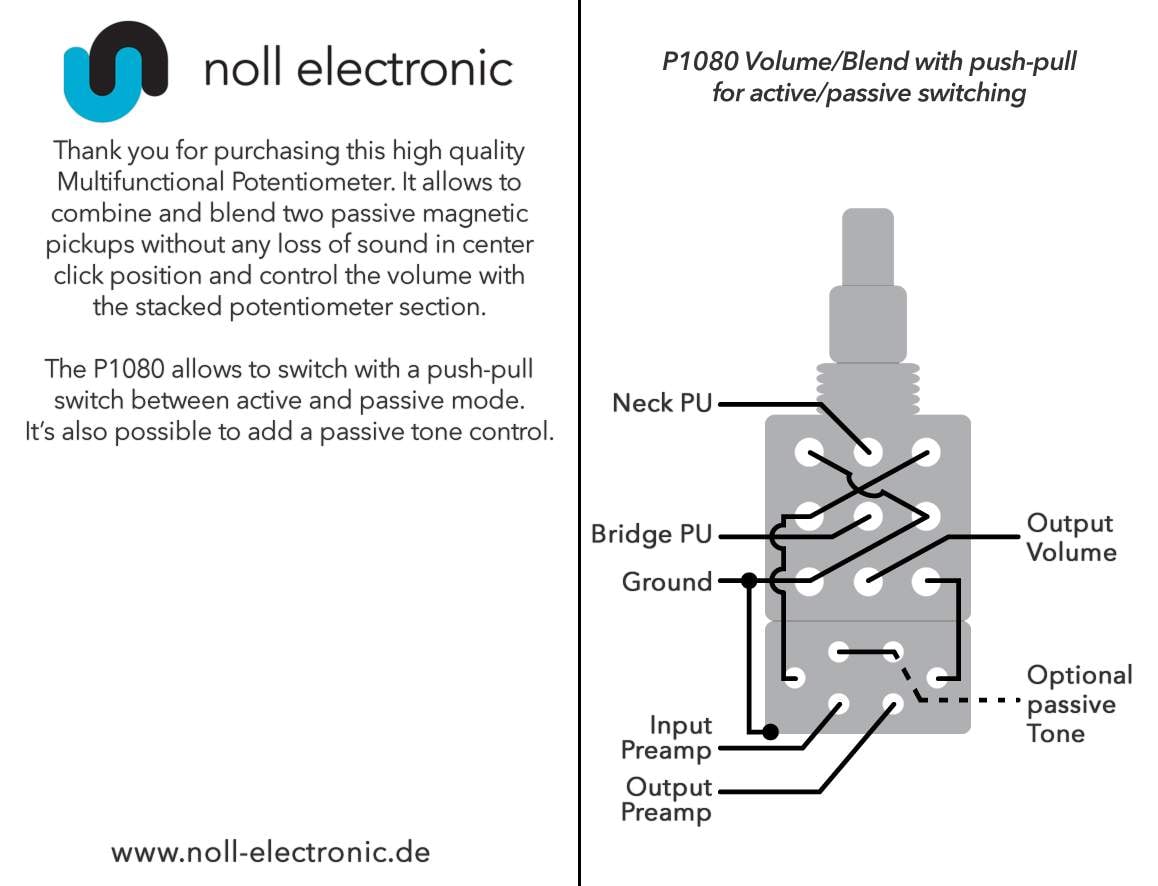
The "Output Volume" pin is the hot of the circuit and goes to the tip of the jack, right? The preamp in and out have corresponding lugs on the preamp board so I'm pretty confident I'm right, but couldn't hurt to get confirmation before running this thing
)Here is the diagram for the vol/blend pot:
The "Output Volume" pin is the hot of the circuit and goes to the tip of the jack, right? The preamp in and out have corresponding lugs on the preamp board so I'm pretty confident I'm right, but couldn't hurt to get confirmation before running this thing
Last edited:
Are you using the active/passive function?Since I have the opportunity I want to make sure an assumption I'm operating under is, in fact, correct (gonna tag @AudioTaper but anyone please feel free to chime in
Here is the diagram for the vol/blend pot:
View attachment 4106127
The "Output Volume" pin is the hot of the circuit and goes to the tip of the jack, right? The preamp in and out have corresponding lugs on the preamp board so I'm pretty confident I'm right, but couldn't hurt to get confirmation before running this thing
I'll have to look up the pot, but it looks like you are correct. I'll have to check it in a bit but I didnt want to leave you hanging

Passinwind
I know nothing.
- Dec 3, 2003
- 23,093
- 46,079
- Disclosures
- Designer/Toaster Tech @ Passinwind Electronics
@Passinwind might know as well, I'm pretty sure he uses/has used the Noll pots
I've used quite a few, but not that one. But I'm pretty sure that's correct. I'll check my Noll documents when I get back on my desktop computer later this evening, I don't have 'em on my iPad.
You guys rock!
And yes, I am using the active/passive push/pull feature
And yes, I am using the active/passive push/pull feature
No way, YOU ROCK!!You guys rock!
And yes, I am using the active/passive push/pull feature
Now the kids arent bugging me for food, I had a chance to look at it. Look at the solder lugs this way
Blend on top, standard wiring with 1 out and 1 ground
Volume in the middle, still pretty standard
DPDT switch on l the bottom. Its also wired pretty much as a standard bypass
I color codes it to break it down
And if you want to look at it as a wiring diagram (sorry, it's a little messy...)
BUT unless I'm missing something, it looks like the lugs on the blend are wired backwards. I would check it with a DMM to verify which way is bridge and which way is neck.
This also has the volume after the preamp switch and the preamp input is left open when it's in passive mode. I usually see the selector after the volume and the preamp input is grounded when it's in passive mode. This is also how Nordstrand suggests it is wired.
So to do it this way, you would do this. Ground is in green, signals are in blue. Theres also a jumper on the switch section, so watch that.
Do you have enough slack to wire is loose and test it (and make sure the blend directions are correct and such)?
Are you planning on having a passive tone?
No way, YOU ROCK!!
Now the kids arent bugging me for food, I had a chance to look at it. Look at the solder lugs this way
Blend on top, standard wiring with 1 out and 1 ground
Volume in the middle, still pretty standard
DPDT switch on l the bottom. Its also wired pretty much as a standard bypass
I color codes it to break it down
View attachment 4106376
And if you want to look at it as a wiring diagram (sorry, it's a little messy...)
View attachment 4106378
BUT unless I'm missing something, it looks like the lugs on the blend are wired backwards. I would check it with a DMM to verify which way is bridge and which way is neck.
This also has the volume after the preamp switch and the preamp input is left open when it's in passive mode. I usually see the selector after the volume and the preamp input is grounded when it's in passive mode. This is also how Nordstrand suggests it is wired.
So to do it this way, you would do this. Ground is in green, signals are in blue. Theres also a jumper on the switch section, so watch that. View attachment 4106432
Do you have enough slack to wire is loose and test it (and make sure the blend directions are correct and such)?
Are you planning on having a passive tone?
No passive tone, I really only want the passive opinion as a safety net for battery failure. Checking the blend direction is easy enough. Im not sure I understand the preamp input left open in passive mode. Is that something that puts the electronics at risk? I have some understanding of these components, but mostly just the ability to follow diagrams
Darkglass shows the bypass after volume in their diagrams.Since you've taken a look at this, the preamp input indicates that pin goes to the preamp input, yes? (In other words its not the input to the switch from the preamp and should go the the "out" lug on the pre). The same question about the preamp output pin (except reversed
)
Last edited:
In other electronics, an unused amplifier input is grounded to avoid oscillation and amplifying noise on the line. Can it damage it? Not sure, but I wouldnt chance it myself. Not for Darkglass prices...No passive tone, I really only want the passive opinion as a safety net for battery failure. Checking the blend direction is easy enough. Im not sure I understand the preamp input left open in passive mode. Is that something that puts the electronics at risk? I have some understanding of these components, but mostly just the ability to follow diagrams
Since you've taken a look at this, the preamp input indicates that pin goes to the preamp input, yes? (In other words its not the input to the switch from the preamp and should go the the "out" lug on the pre). The same question about the preamp output pin (except reversed
I hate when manufacturers use wording like in and out... give us better direction! I used To and From Preamp in my sketch, I think it makes things more clear.
But to answer your question, in this case use IN as in to the preamp. Preamp out is Out from the preamp.
Wow, this is all crazy confusing and makes me cringe over my plan to use the same Darkglass pre in my build. 


It's the pot that's confusing bit, and Noll's instructions. The Darkglass instructions are pretty straightforwardWow, this is all crazy confusing and makes me cringe over my plan to use the same Darkglass pre in my build.
Last edited:
Yeah, my plan is to use the Darkglass tone capsule and 3 Nordstrand "Dingwall" pups with an active/passive switch. But I may just go mini-toggle for the switch because that thing has me totally confused, plus I'm not sure I have enough depth to house that thing, it looks CRAZY tall!I
It's the pot that's confusing bit, and Noll's instructions. The Darkglass instructions are pretty straightforward
I'm also tempted to try Darkglass preamp. Looking forward for your thoughts about it.
@AudioTaper
I've decided the smart thing to do is redo the pot in line with the Darkglass instructions now that I understand it better. I'm gonna draw it up and post it but I want to make sure of a couple things 1st. One is that the following are equivalent so I understand the layout of the DPDT switch:
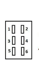

(Just the pins, ignoring the wires drawn on the noll diagram)
Two is that I think the switch and therefore its wires are upside down on my pot from this Darkglass schematic:
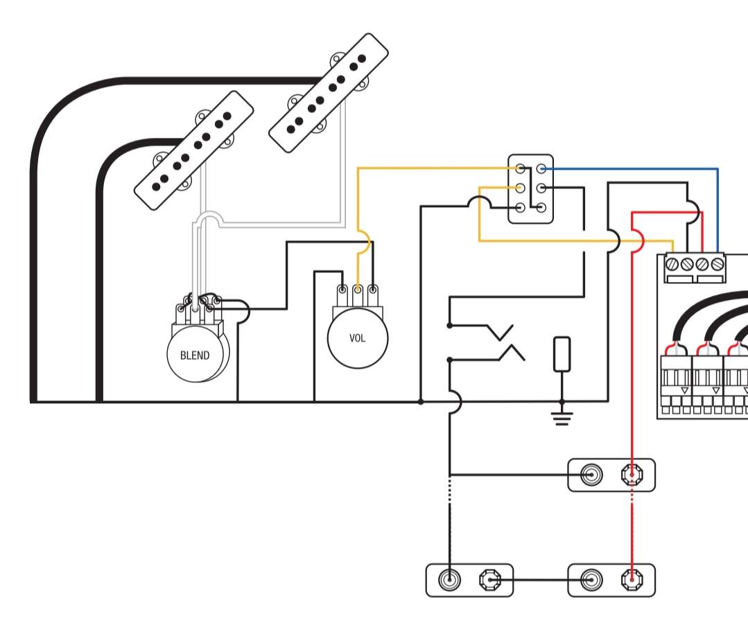
Essentially I want to make sure push is active and pull is passive
I've decided the smart thing to do is redo the pot in line with the Darkglass instructions now that I understand it better. I'm gonna draw it up and post it but I want to make sure of a couple things 1st. One is that the following are equivalent so I understand the layout of the DPDT switch:
(Just the pins, ignoring the wires drawn on the noll diagram)
Two is that I think the switch and therefore its wires are upside down on my pot from this Darkglass schematic:
Essentially I want to make sure push is active and pull is passive
Last edited:

Essentially I want to make sure push is active and pull is passive
Got that setup on my Mensinger......Would prefer it t'other way.....
I would verify the switch with a DMM, but it looks like that would be correct.@AudioTaper
I've decided the smart thing to do is redo the pot in line with the Darkglass instructions now that I understand it better. I'm gonna draw it up and post it but I want to make sure of a couple things 1st. One is that the following are essential equivalent so I understand the layout of the DPDT switch:
View attachment 4108809
View attachment 4108819
(Just the pins, ignoring the wires drawn on the noll diagram)
Two is that I think the switch and therefore its wires are upside down on my pot from this Darkglass schematic:
View attachment 4108808
Essentially I want to make sure push is active and pull is passive
Yeah, the Noll layout looked (again, verify with a DMM) like the pots were backwards. I would just follow the Darkglass wiring, it's the same as the Nordstrand I posted in post #168
I thought that might be the case, but I figured I'd draw it for my own practiceI would just follow the Darkglass wiring, it's the same as the Nordstrand I posted in post #168
Ok fans of tedious wiring you'd rather just pay someone else to do
I tested some things out on the fancy pot, confirmed the blend is correct the way Noll has it on their diagram, pulled it and the Darkglass drawing up, and got to making my own (admittedly crude) diagram. I tried to use critical thinking here by using Noll's diagram to make sure I have the send from the blend section and the input to the volume section correct. I can also see from their diagram that the bottom pins on the DPDT switch are the active mode. I'm pretty confident I've got this right (@AudioTaper please double check me) and I'll explain my thinking after the pic. So here goes:

So again, I'm using this Noll diagram to determine out of the blend and into the volume:
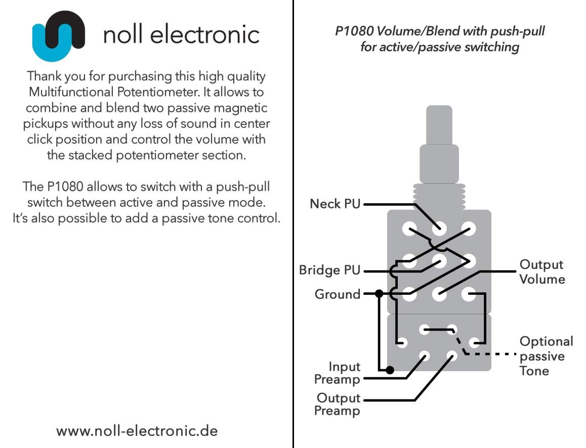
If that is correct then here is how things work in active mode: volume outputs to pin 6 (the jumper to pin 1 doesn't matter cause pin 1 isn't connected in this position) which is connected to pin 4 sending the signal to the preamp. It returns on pin 5 which in that mode is connected to pin 3 sending it to the output jack.
In passive mode volume outputs to pin 6 which isn't connected so the jumper takes it to pin 1 which is. Pin one is connected to pin 3 which sends it right to the jack. Meanwhile in that position pin 4 is connected to pin 2, grounding the preamp's input.
I have the preamp send and return labeled Y (Yellow) and B (Blue) cause thats the colors used in the Darkglass diagram:

My brain says this is the way to go, what say you TB?
I tested some things out on the fancy pot, confirmed the blend is correct the way Noll has it on their diagram, pulled it and the Darkglass drawing up, and got to making my own (admittedly crude) diagram. I tried to use critical thinking here by using Noll's diagram to make sure I have the send from the blend section and the input to the volume section correct. I can also see from their diagram that the bottom pins on the DPDT switch are the active mode. I'm pretty confident I've got this right (@AudioTaper please double check me
) and I'll explain my thinking after the pic. So here goes:So again, I'm using this Noll diagram to determine out of the blend and into the volume:
If that is correct then here is how things work in active mode: volume outputs to pin 6 (the jumper to pin 1 doesn't matter cause pin 1 isn't connected in this position) which is connected to pin 4 sending the signal to the preamp. It returns on pin 5 which in that mode is connected to pin 3 sending it to the output jack.
In passive mode volume outputs to pin 6 which isn't connected so the jumper takes it to pin 1 which is. Pin one is connected to pin 3 which sends it right to the jack. Meanwhile in that position pin 4 is connected to pin 2, grounding the preamp's input.
I have the preamp send and return labeled Y (Yellow) and B (Blue) cause thats the colors used in the Darkglass diagram:
My brain says this is the way to go, what say you TB?
I have a bunch of free time today, and I was feeling good about the logic which led to my wiring plan so...
I wired it that way

And... it works (at least in passive mode, still gotta get a tiny screwdriver to hook up the pre but I'm pretty sure it will work
  ).
).
I decided to double check my battery wiring before connecting to the preamp, and I was freaked out when the meter read 0 volts... until I noticed I had it set to AC (last time I read voltages I was doing wiring in my house). Fixed that and two fresh 9 volts read:

Of course, things were not problem free, but this is not my fault. The solid shafts on the Noll (or should I say MEC, noticed it says MEC right on it...) pot are hard to grip and turn with your fingers. Easy fix right? Just put the concentric knobs I bought with it on. Well, the bottom knob won't sit level with the set screw tightened
It's fine just sitting there:

Not so much with the screw tight:

The other black dome knobs I've got work fine on the EQ pots, and I'm still liking the look:

I'm gonna email Best Bass Gear and see what they'll do for me. Their site says this is the only knob set that will work but I'd bet Warwick knobs will work just fine
I could rob the set from my vette just to test my theory, might do that tomorrow.
Happy new year TB!
I wired it that way
And... it works
(at least in passive mode, still gotta get a tiny screwdriver to hook up the pre but I'm pretty sure it will work ).I decided to double check my battery wiring before connecting to the preamp, and I was freaked out when the meter read 0 volts... until I noticed I had it set to AC
(last time I read voltages I was doing wiring in my house). Fixed that and two fresh 9 volts read:Of course, things were not problem free, but this is not my fault. The solid shafts on the Noll (or should I say MEC, noticed it says MEC right on it...) pot are hard to grip and turn with your fingers. Easy fix right? Just put the concentric knobs I bought with it on. Well, the bottom knob won't sit level with the set screw tightened
It's fine just sitting there:
Not so much with the screw tight:
The other black dome knobs I've got work fine on the EQ pots, and I'm still liking the look:
I'm gonna email Best Bass Gear and see what they'll do for me. Their site says this is the only knob set that will work but I'd bet Warwick knobs will work just fine
I could rob the set from my vette just to test my theory, might do that tomorrow.
Happy new year TB!


