• TalkBass has been independent since 1998. Add your voice.
    Create a free account to reply to discussions, view embedded media, and browse with fewer display ads.
    Join freeLog in
    Want zero display ads or expanded classifieds tools? Compare plans.

Official Ampeg Portaflex Club

Sorry guys, I miscounted numbers and screwed up the numbering on this page. I've edited the previous posts to reflect the new numbers but here they are anyway...

#107 jeefberky
#108 bassgasser
#109 Washishimi
#110 Standalone
#111 brekfustuvluzer
 
Finally a few pics of the project....
 

Attachments

  • b15begins_r.jpg
    b15begins_r.jpg
    53.6 KB · Views: 168
  • b15build_r.jpg
    b15build_r.jpg
    73.6 KB · Views: 160
  • Like
Reactions: GreaserMatt
Finally a few pics of the project....

Jeef,

Thanks for sharing photos of your work - it looks great! I would love to be smart enough to do what you are doing. I think it would be so cool to have a rig (amp+cabinet) that I could say I built myself. I guess the problem then would be wanting to hand-build a bass to go along with everything else!

I have some questions for you about your amp.

1) What is the switch for on the rear? You had mentioned adding a switch for the bias circuit; is that it or is it for something else?

2) What kind of hardware are you using at the main speaker out? I couldn't quite tell what it was from the photo.

3) Did you have the chassis fabricated or were you able to start with something off the shelf? How does its footprint compare to a real B15N chassis? (it looks like it might be slightly larger...)

It looks like a great project - I hope you continue to share!
 
Does anyone know where to get a reissue? I had a 70s model a long time ago, and I sold it because at the time, it simply wasn't loud enough to be used in any band situation. I've regretted that decision ever since.

Keep checking the usual Ebay, Craigslist and the TB classifieds. Don't see them very often but they do pop up. You see originals more than the reissue these days, which I guess makes sense since the original was out for 20 years and the reissue was only out for 7 or 8.
 
Mark, thanks for the nice comments.. I do indeed have a custom bass in mind for this setup... it was the reason I built the b-15 to begin with!

1. The switch on the rear was intended for fixed and cathode bias changing. In retrospect I think it would be more keen to put it up front where the ground switch used to be and not use a pilot light at all. I may do this if I redo the chassis.

2. The main speaker out is a standard switchcraft 12A jack-- ring, tip and sleeve. This connects to a switchcraft 13A "transfer circuit" jack used for the ext. jack. Essentially, when anything is plugged into the external you get 16 ohms in series between the two jacks. This made it so that I couldn't do the safety ground feature. I wanted a streamlined look to the chassis that didn't have cords permanently attached. So I went this way. A XLR jack would've been ideal, but I didn't know where to get them when I started the build. The back features are: Power connector, fuse, hum balance, main speaker, ext. speaker, and ext. amp. I opted to put the hum balance pot near the power tubes, since the wire on lug 2 comes off of the power tubes. On the originals it was mounted near the preamp tubes. I wonder why.

3. The chassis is a standard Hammond manufactured steel chassis, 16 x 8 x 2. It was the best I could do without having to fab my own. I did the punching and polishing (it came with this awful grey color as shown in one of my earlier photos of the project) and that was enough work for me. I think I may just have one made to true specs if I do go ahead and start over. This is a problem when trying to make a cabinet to one of your specs... The chassis tray has to be larger, the flipping top needs to be larger, so the side rails need to be smaller. Also, it is a flat face, rather than angled, so knobs need more clearance to flip the top. Small aesthetic problems that I need to work out before I start making the cab.

Does anyone have the proper specs for the chassis? L x W x H?
 
Jeef,

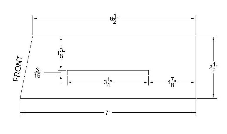
I measured some of the heads I have here and the dimensions seemed to vary between them, about 1/16" either way. On average I got 16-1/16" wide, but to me 16" seems to make more sense. The variation seemed to depend on how well the side pieces were fit in. Here's a drawing of the side view:

b15n_chassis.jpg


The angle of the front face relative to the bottom comes out to be about 79 deg. It looks like your chassis is okay width-wise; it's the depth that's hurting you. I think you could pick up most, if not all, of what you need by expanding the cabinet top opening forward.

I've always wanted to have a custom chassis made. I've looked at a couple places that do rapid sheet metal prototyping but I've never gotten a price. I think if I ever did it I would have a custom face plate made too. It seems like it would be easier and more durable than trying to silk screen the chassis like Ampeg did.
 
Finally a few pics of the project....
Jeef,

I was just looking again at the photos you posted, particularly the one showing the inside of the amp (with the soldering iron next to it). What's the story with the piece of wood you're using to work on? The grain is beautiful!
 
Mark,
The wood is a slab of curly cherry i picked up on ebay. It's my coffee table... my first furniture project. The amp cabinet will definitely be either cherry or walnut with dovetails around the sides and dados to hold the baffle and back, depending on the availability of cherry in that width. I will try to expose as much of the natural edge of the tree as I can in the finished cab.
 
Here's a drawing of the side view:

b15n_chassis.jpg

Mark: My '63 chassis has more or less the same measurements except it is slightly smaller front to back. It is 6 3/8" at the top instead of 6 1/2", the bottom measures 6 13/16" instead of 7". They probably varied from one batch to the next. My amp tray is just under 7" deep so a more recent chassis wouldn't fit on my cab.

Jeef: I often use Weber chassis. They are very well made. There are mechanical drawings available Invalid Link Removed that are worth checking out. There are also some interesting blank chassises and boards available from Watts Tube Audio. Perhaps one of these could be adapted for a B-15 project.


David
 
1. The switch on the rear was intended for fixed and cathode bias changing. In retrospect I think it would be more keen to put it up front where the ground switch used to be and not use a pilot light at all. I may do this if I redo the chassis.

If you decide to go with just one type of bias, you could use the switch to select between two different levels of bias.

I opted to put the hum balance pot near the power tubes, since the wire on lug 2 comes off of the power tubes. On the originals it was mounted near the preamp tubes. I wonder why.

I don't think that it matters where it is placed. In amps, you often see hum pots or artificial centre taps at the end or the beginning of the heater string. Bus lines often have termination resistors at the end to suppress ringing. This doesn't apply at standard heater frequencies though. In the case of the B-15, I suspect that they put it at that location because it is a big pot and fits well there.


David
 

Latest posts