Just out of curiosity, I had a look at the Service Manual schematics for the Rumble 200 (the Service Manual covers the Rumble 40, 100, 200 and 500).
Available here:
https://www.fmicassets.com/Damroot/Original/10002/Rumble 200 V3 Schematics-Diagrams.pdf
The "crossover" and switch for the Rumble 200's horn consists of a 1uf/250volt film capacitor, an 8.2 ohm 5 watt (10% tolerance) resistor, and a switch in series.
Here is a simplified version of the diagram in the Service Manual:
View attachment 7317654
The resistor; the capacitor; the connection points for the jumper wires from the ICEPower module; and to the horn switch; as well as the output connector to the speaker and horn are all located on the bottom section of the Input/Output board, which is mounted on the back panel:
View attachment 7317669
So, if you were careful, it WOULD be possible to "saw off" the bottom section of the Input/Output board that contains the components and redo the proper connections,
BUT, I think that it would be EASIER to just buy the appropriate value resistor and film capacitor and a SPST switch.
Or desolder and re-use the originals.
Connect the four speaker wires from the P106 output connector together so that the speaker and horn are connected in parallel
(RED and WHITE positive wires together, and the two BLACK negative wires together).
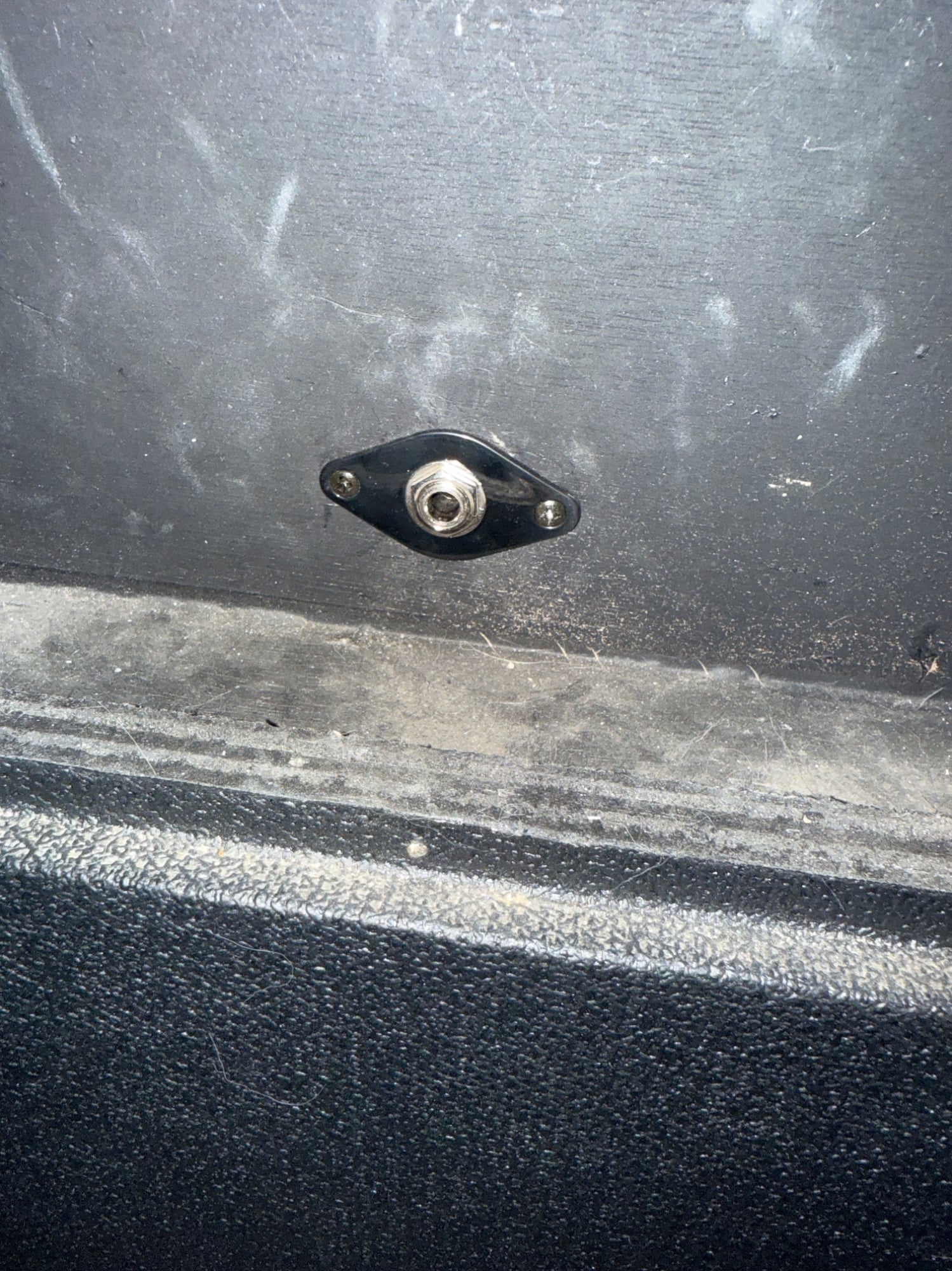
Connect the parallel pairs to a 1/4" TS jack mounted on the back of the cab (RED & WHITE wires to TIP, and BLACK & Black wires to sleeve).
Then cut the RED positive wire between the jack and the horn, and splice in the capacitor, resistor, and SPST switch in series.
Mount the switch on the back panel with the jack.
Shouldn't be very difficult.
Now running and hiding from Agedhorse....