• TalkBass has been independent since 1998. Add your voice.
    Create a free account to reply to discussions, view embedded media, and browse with fewer display ads.
    Join freeLog in
    Want zero display ads or expanded classifieds tools? Compare plans.

Repurposing a broken Rumble 200

I bought this crossover, cheap and probably crappy specs, installed it.
Horn set to highest suppression, and set the bass jumper for no attenuation.
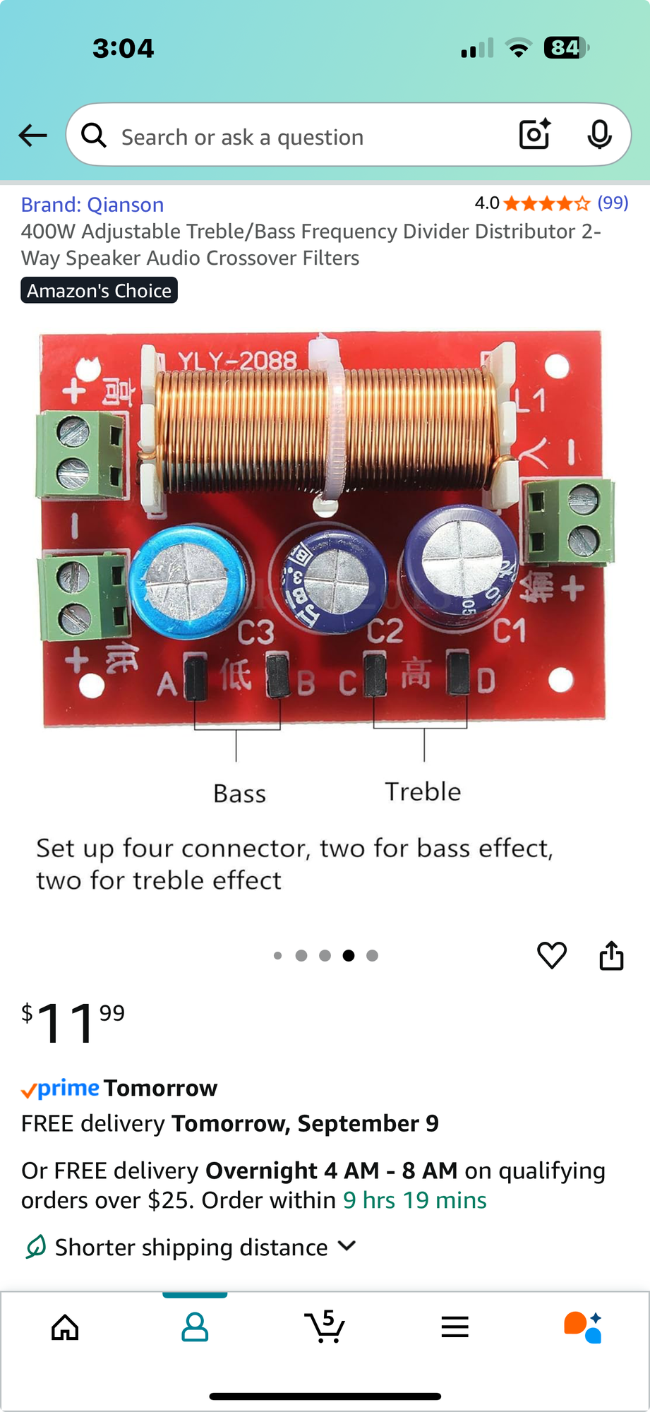
1757369074268.png


I got it for 8.99.
It works really well in a short test with my 20 (10 into 8ohm) watt and 150 watt amps.
Done have just a touch of the piezo in play, just like I wanted.

I now have 50.00 total invested for a practice amp /cab that could serve a small gig with my higher wattage amp.

 
I bought this crossover, cheap and probably crappy specs, installed it.
Horn set to highest suppression, and set the bass jumper for no attenuation.

View attachment 7317755

I got it for 8.99.
It works really well in a short test with my 20 (10 into 8ohm) watt and 150 watt amps.
Done have just a touch of the piezo in play, just like I wanted.

I now have 50.00 total invested for a practice amp /cab that could serve a small gig with my higher wattage amp.
Nowhere near 400 watts, this caps will poopie the bed quite quickly.
 
I don't know how I missed all of this conversation, but my plan at this point would be to run the wires from the woofer over to the Ext. Speaker input, since that should be beefy enough to handle the current (it's expected to handle it on the way out, right?), disconnect any other wires to any jacks, and ignore the tweeter.

When I look inside, if it looks easy enough to run from the Ext. Speaker to the amp side of the crossover, maybe I'll do that, but probably not. I'm just planning on using this to get some extra oomph out of my good 200.
 
I finally got around to opening the Rumble up. The connector from the board to the speakers has four wires (see picture), but I can't figure out how to get inside the cabinet to get to the actual speakers.

Could I connect a jack to two of those wires? Which two? Or, how can I get inside the cabinet? Or, does the Rumble have a fuse and could that be the problem?
 

Attachments

  • 20251005_095546.jpg
    20251005_095546.jpg
    1.2 MB · Views: 19
OK, I found a really detailed diagram. There doesn't seem to be a fuse, but I did find that the white and black wires on that connector connect to the woofer (the red and black connect to the tweeter). So, hypothetically, I could cut those from the connector and solder a new speaker jack to those wires, figure out a way to mount it and I'm all good.

How many ways is that wrong?

Here's the diagram (warning, PDF): https://www.fmicassets.com/Damroot/Original/10002/Rumble 200 V3 Schematics-Diagrams.pdf

Edited to add: I found this super thin wire just floating in space, which looked burned out on one end -- could that be some sort of fuse?
 
Last edited:
Take the woofer out from the front.
Pull off the spade connector ensuring you know or mark the polarity.

Disconnect the tweeter at the spade connectors : it’s way too loud to be useful without a crossover or LPad. There is plenty of highs from the woofer.

Drill a hole large enough for a standard jack to fit in. Buy or fashion a jack plate
solder jack to a pair of wires, verifying polarity.
Insert jack into cabinet.
Reattach the woofer via the spade connection.
Screw the woofer back into the cabinet.

:)
 
  • Like
Reactions: five7
OK, I found a really detailed diagram. There doesn't seem to be a fuse, but I did find that the white and black wires on that connector connect to the woofer (the red and black connect to the tweeter). So, hypothetically, I could cut those from the connector and solder a new speaker jack to those wires, figure out a way to mount it and I'm all good.

How many ways is that wrong?

Here's the diagram (warning, PDF): https://www.fmicassets.com/Damroot/Original/10002/Rumble 200 V3 Schematics-Diagrams.pdf

Take the woofer out from the front.
Pull off the spade connector ensuring you know or mark the polarity.

Disconnect the tweeter at the spade connectors : it’s way too loud to be useful without a crossover or LPad. There is plenty of highs from the woofer.

Drill a hole large enough for a standard jack to fit in. Buy or fashion a jack plate
solder jack to a pair of wires, verifying polarity.
Insert jack into cabinet.
Reattach the woofer via the spade connection.
Screw the woofer back into the cabinet.

:)
I cannot figure out how to take the woofer out - I unscrewed all the screws around the perimeter and it didn't want to budge. Just try harder?
 
I cannot figure out how to take the woofer out - I unscrewed all the screws around the perimeter and it didn't want to budge. Just try harder?
The foam seal may have bonded slightly to the baffle. You can pry by using a large dull flat blade and twist, don’t lever.

Move around the perimeter till you find the weak spot, it should not take Lots of pressure.
 
OK, I found a really detailed diagram. There doesn't seem to be a fuse, but I did find that the white and black wires on that connector connect to the woofer (the red and black connect to the tweeter). So, hypothetically, I could cut those from the connector and solder a new speaker jack to those wires, figure out a way to mount it and I'm all good.

How many ways is that wrong?

Here's the diagram (warning, PDF): https://www.fmicassets.com/Damroot/Original/10002/Rumble 200 V3 Schematics-Diagrams.pdf

Edited to add: I found this super thin wire just floating in space, which looked burned out on one end -- could that be some sort of fuse?
That’s fine.

No, there should be no burned wire, that’s never ever allowed to be used as a fuse of any type.


Take the woofer out from the front.
Pull off the spade connector ensuring you know or mark the polarity.

Disconnect the tweeter at the spade connectors : it’s way too loud to be useful without a crossover or LPad. There is plenty of highs from the woofer.

Drill a hole large enough for a standard jack to fit in. Buy or fashion a jack plate
solder jack to a pair of wires, verifying polarity.
Insert jack into cabinet.
Reattach the woofer via the spade connection.
Screw the woofer back into the cabinet.

:)
Without a crossover, the tweeter will fail in seconds or minutes.
 
Last edited:
  • Like
Reactions: WRM
I'll try and post a picture of the very thin loose wire this weekend. I think my current plan is to cut the black and white connectors in my picture above, since those apparently go to the woofer. I'll measure the resistance -- should be 8 ohms, right? Then, connect them to a 1/4 inch jack, that I'll mount there somewhere.

Can someone post a link to a speaker-level jack and short quarter-inch speaker cable? I tried searching on Sweetwater, but I couldn't find the right terms. Are there easy-wire jacks, or will I have to bust out the soldering iron?
 
No, it should be about 5.7 ohms IIRC, that's the DC resistance. 8 ohms is the NOMINAL impedance. Two different things.

1/4" jacks are solder-on.

Typically below 3' are custom in the speaker cable world.
 
No, it should be about 5.7 ohms IIRC, that's the DC resistance. 8 ohms is the NOMINAL impedance. Two different things.

1/4" jacks are solder-on.

Typically below 3' are custom in the speaker cable world.
Will any quarter inch jack work, or do I need some kind of beefy one since it's speaker level? And, I'll take a longer cable as long as it can handle speaker level, but the ones I found looked like instrument cables to me.
 
Provided the jack is NOT being mounted on a metal plate with the other jack, any 1/4" tip-sleeve jack will work ok at this power level. Just note that the sleeve of the plug is not at ground when used with a class D or bridged amp, so if you accidentally touch this plug with ANYTHING that's grounded, you could damage your amp.

3' speaker cables are standard: