
soldered all the components. easier than I thought. after soldering the bass pot wires the RatShack tip disintergrated  oh well, almost done
oh well, almost done 
TalkBass has been independent since 1998. Add your voice.
Create a free account to reply to discussions, view embedded media, and browse with fewer display ads.
Join free Log in
Want zero display ads or expanded classifieds tools? Compare plans.
oh well, almost done
 I can't believe I did it! Just think, I never tinkered with the electronics in a bass in my life until a few months ago. I found the source of the voltage leak with the other preamp. A wire has to run from the battery negative to the green ground wire from the preamp. When I severed that connection the voltage leak came back. So the preamp I bought from ebay works fine. The diagram was wrong because it didn't have that ground connection. The Bajaman diagram is the only one that seems to be correct. I guess being a noob I have to pay my dues and learn as I go. THANKS Uncle FluffY!
Congratulations, but you know the rules ... no pics, no homebrew preamp ...

A wire has to run from the battery negative to the green ground wire from the preamp... The diagram was wrong because it didn't have that ground connection... I guess being a noob I have to pay my dues and learn as I go.

Yes you do pay dues as you go when you are just starting out.
Here's a tip. That diagram is not wrong.
It assumes you are using a conductive material as a ground buss like a Stingray control plate or a pick-guard with a metal strip underneath it.
You'll notice that the pots have their grounds terminated to the pot covers and the battery negative is run to the jacks ground lug? If you were using a plastic pick-guard without a metal strip under it you would be effectively severing the ground buss the preamp would not work. So in that case you would have to star ground it wiring everything to the jack lug. If you were just starting out you probably would not know that.



If anyone is interested, here are some photos of the 2-band preamp from a new Classic Stingray.
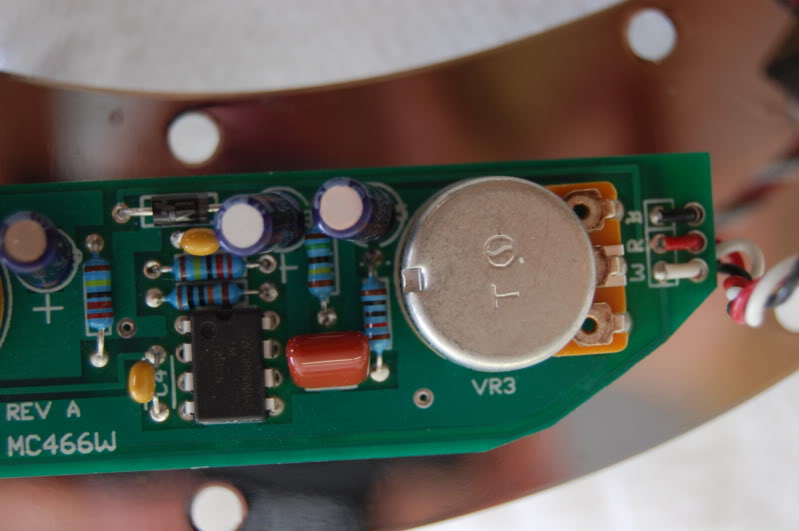
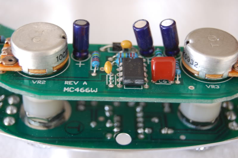
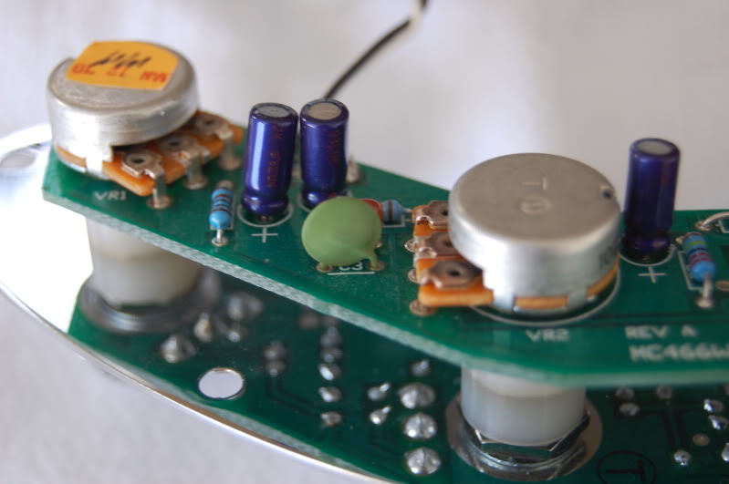

Here's the best closeup I could get of the LM4250CN.
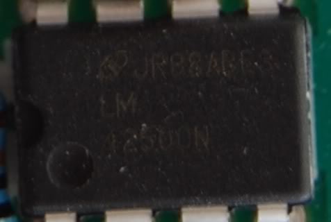
thanks for the pics. looks like they added an inductor? diode? that part must change the tone dramatically. looks like they used quality parts except for the ceramic cap. I see the LM4250CN is there without a socket.
As far as I can tell, it looks like the diode is just in series with the +ve supply to protect against the battery being connected backwards.
what happened to all the enthusiasm? Am I the only one who built a working preamp? newbie luck?


There wouldn't be a chance to obtain one of these boards by now, would it?


