
Totally agreed.I've got 3 basses that I've been "building" for over two years. They're quite dusty from neglect.
The Stingkitty was straight up serendipity on how it came together; things just fell into place, starting with a cheap bass in red/white plaid that practically fell into my lap. I don't think I could produce a copy "cheaply."
First I'd have to buy a bass and paint it. Unless I just left it mono white, or mono red. But that's not a copy, that's an interpretation. Either way, it's guaranteed to be more expensive than the original.
Also, there's no reason he couldn't do something like this on his own. He can make one that is uniquely his, and know the joy from making it with his own hands, rather than paying me to make a carbon copy/interpretation of my vision. It's basically just stickers I found on eBay, after all. They were not expensive.
But, as always, if someone is willing to press sufficient cash into my hand, all things are possible. Fair warning: I may be a ho, but I'm not a crack ho. I cost. Bigly.
EDIT: I just had a brainfart. A Flea (brand) Bass also has a round pickguard, and comes in bright primary colors. This is another possibility for a Hello Kitty bass. Instead of fleas on a cat, a cat on a flea.
I may have just farted a future project into my head!
cc: @Bright Midnight

Enjoy the benefits of a premium membership!
Upgrade Account
-
TalkBass has been independent since 1998. Add your voice.
Create a free account to reply to discussions, view embedded media, and browse with fewer display ads.
Join free Log in
Want zero display ads or expanded classifieds tools? Compare plans.
You are using an out of date browser. It may not display this or other websites correctly.
You should upgrade or use an alternative browser.
You should upgrade or use an alternative browser.
The Mediocre Builders Club
- Thread starter MirandM
- Start date
More options
Who Replied?

Is you Hello Kitty for sale? I don't think I've ever seen a bass quite like it, and to take that bass onto a stage and play heavy stoner with it would kind of give me a kick. I love the way it looks. Come to think of it, I've always had a thing for Hello Kitty. You can call me weird.
I would love to see that bass used in a heavy stoner band.
Well my bathroom is on it's way, I've actually been able to take a shower even though "bass"ically. Still lots of work to do but it's going the right way.

I decided to be really silly this year, and recreate the MPC Outlaw with built in effects, only instead of using plug-in analog modules, I used an Electrosmith Daisy DSP to implement the effects mounted on a PedalPCB Terrarium board to for its signal buffers:
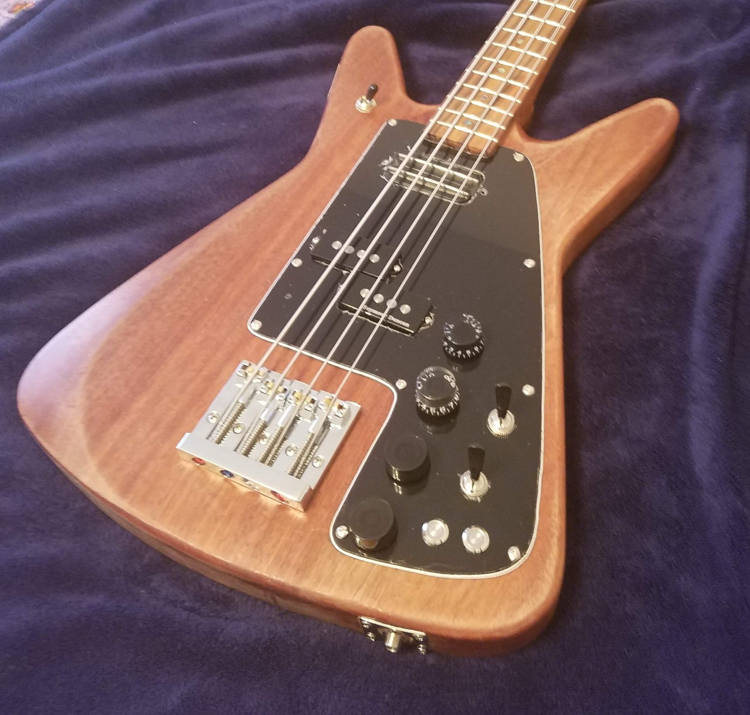
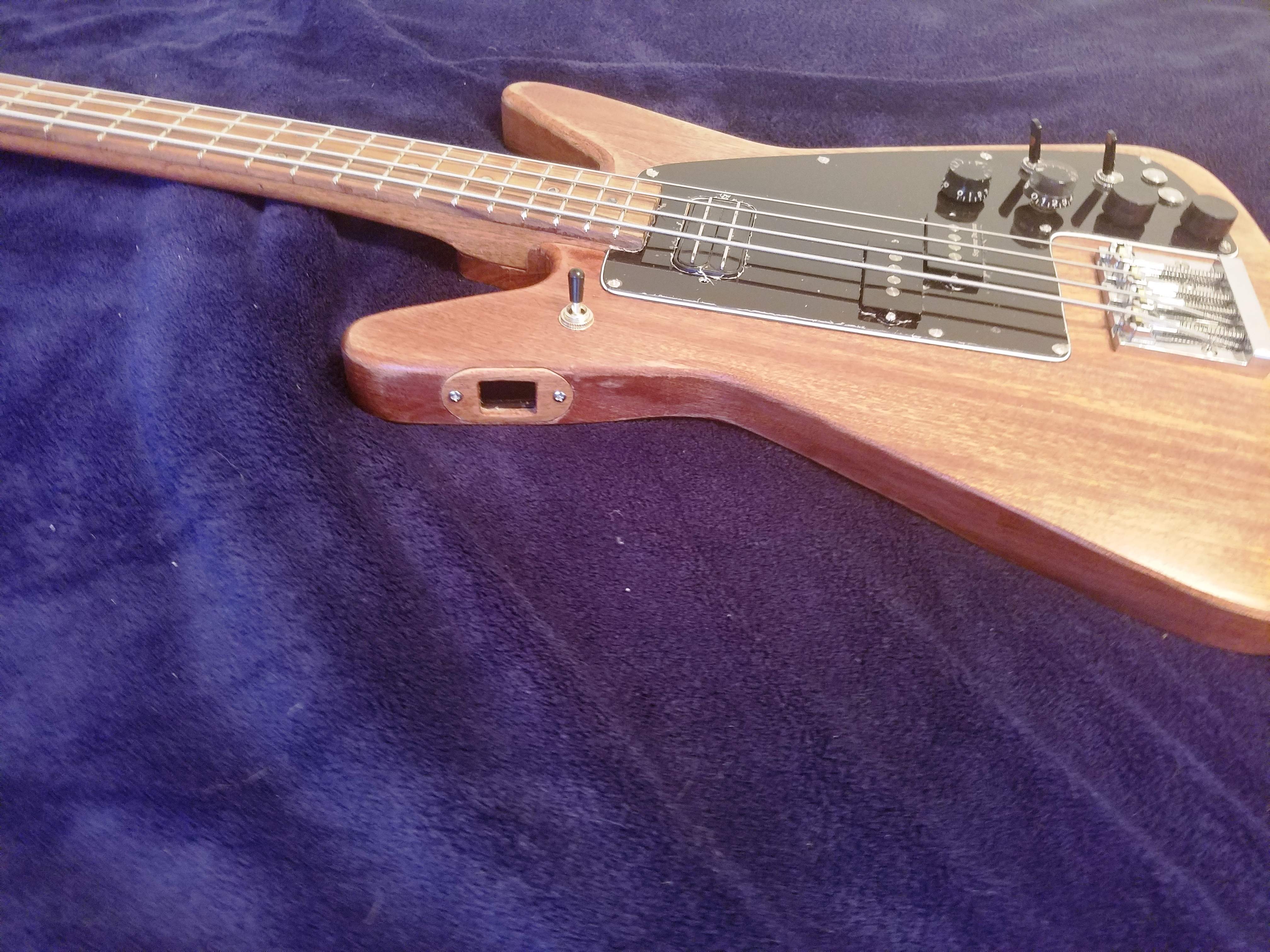
The two bottom knobs are rotary encoders rather than pots, and there's a tiny 0.96" OLED display in the upper horn:
Here's the brains of the operation:
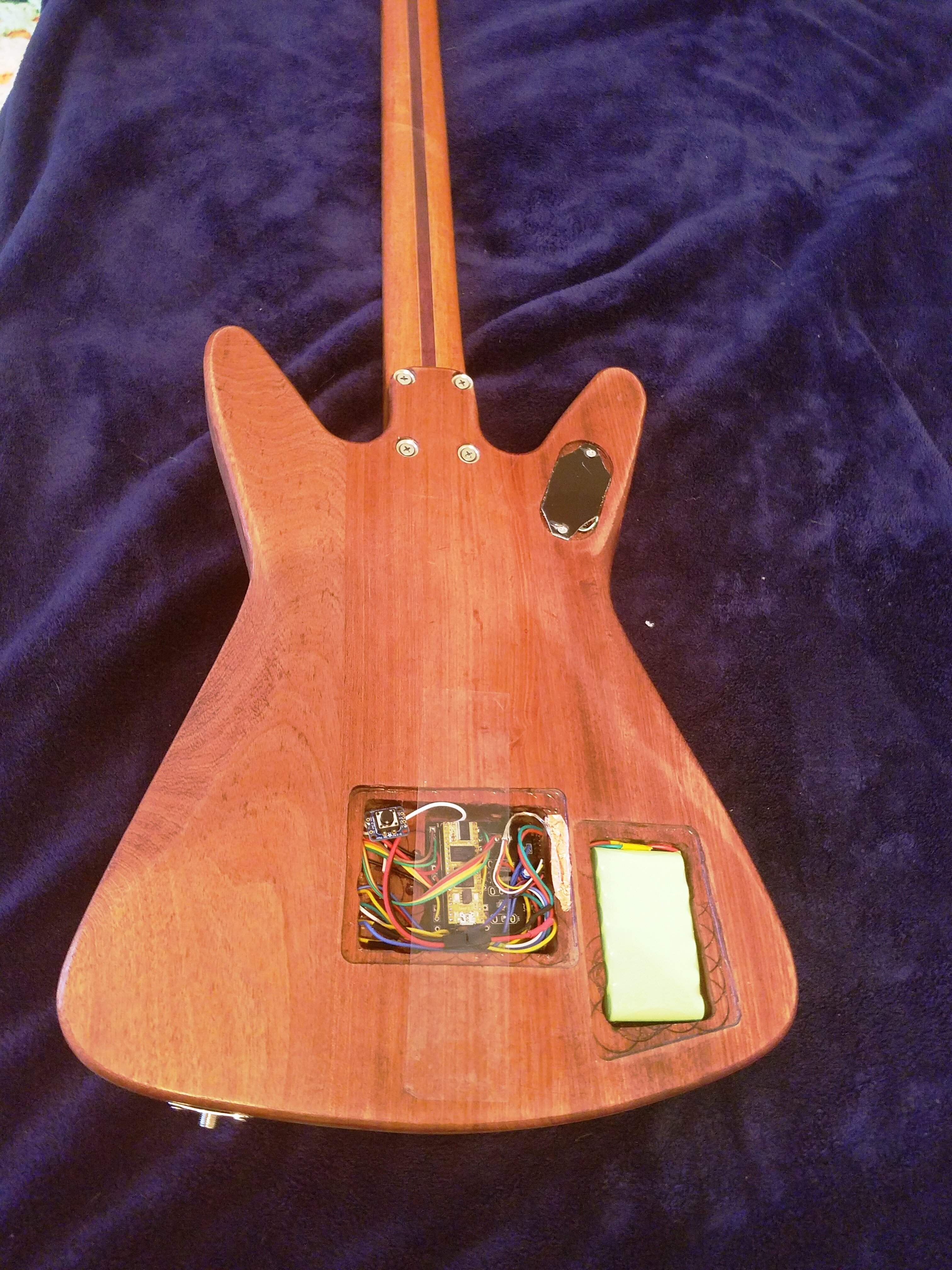
Still some work to do making rear covers, etc. I also plan to put a burst on it to deal with the color mismatch on the display bezel.
The two bottom knobs are rotary encoders rather than pots, and there's a tiny 0.96" OLED display in the upper horn:
Here's the brains of the operation:
Still some work to do making rear covers, etc. I also plan to put a burst on it to deal with the color mismatch on the display bezel.
Last edited:
hello everyone! remember me. my garage/shop has been too cold to work in for a while, but I am back now.
I have started building scarfed joint necks, mostly because i wanted to build an all Sapele bass. Well, all except the pickguard which will be Walnut. The pickguard will be inlaid, flush with the top. Why make a flush pickguard? you might ask. several reasons:
my necks will be 40mm or some 38mm at the nut and 60mm at the heel. 3/4 thick with a 4" wide x 1/2" thick headstock. C shape body.
Part 1 is about how to make the scarf joint.
First, I need a couple fixtures or jigs... I will make everything from 6/4 lumber (1-1/2" thick). In this example I used a piece of sapele 7" wide by 48" long.
first jig... I need to assure that My pieces are all uniform sizes. Rather than trusting my cheap table saw fence to be consistent, and my eye to be true, I made a fence that uses the guide slot in the saw table to assure that it is always the same. the plywood fastened to the side fits down into the slot, holding the jig in place.
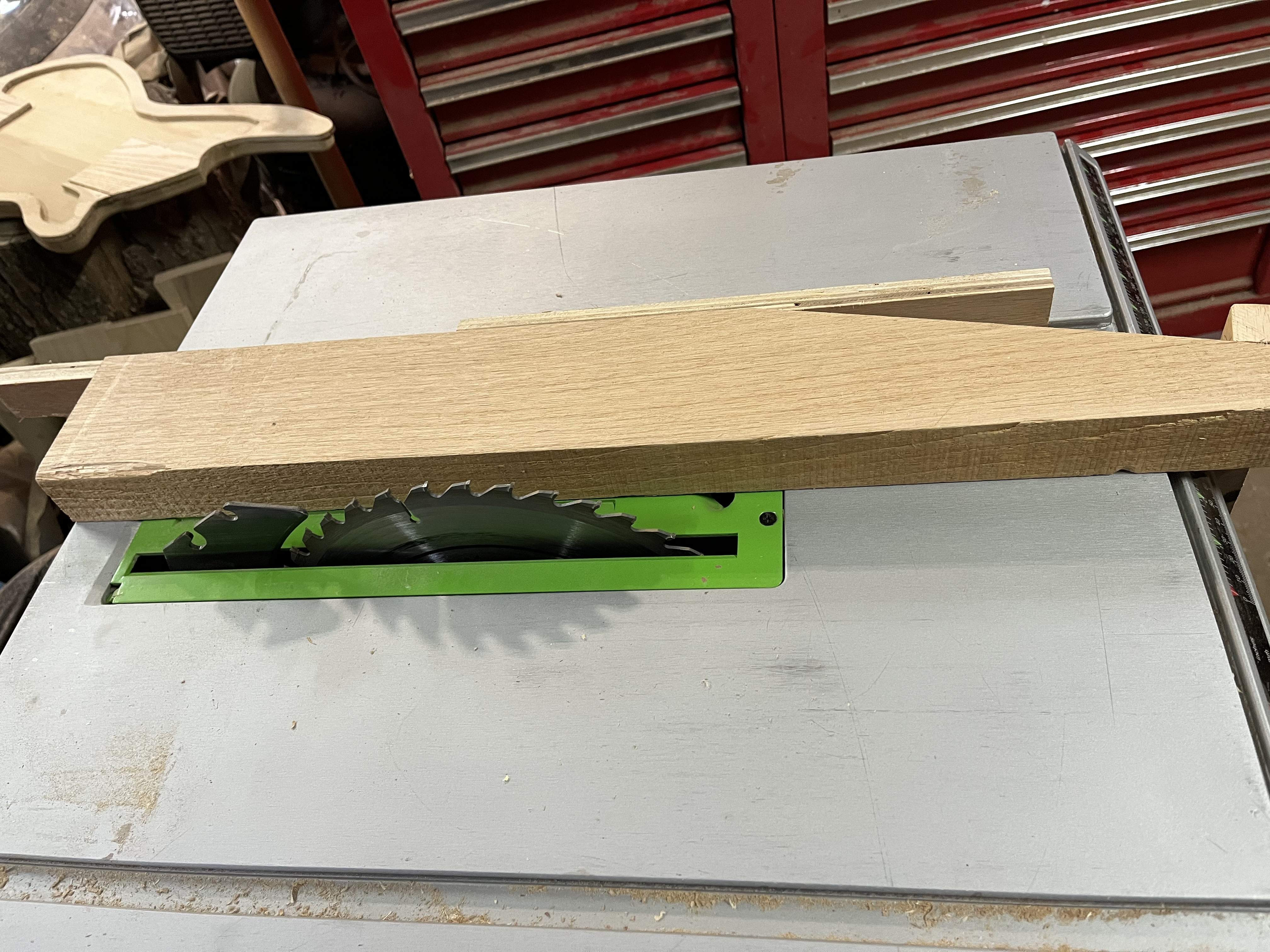
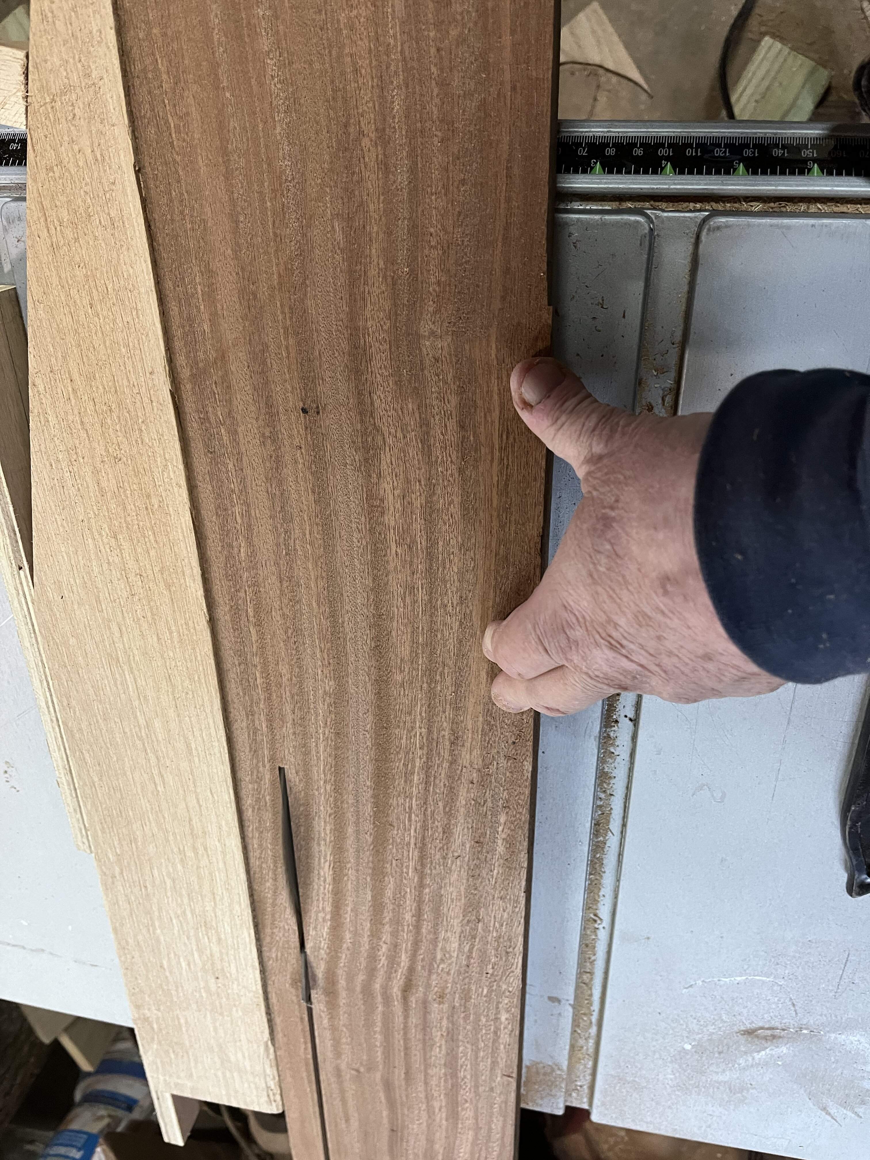 After ripping the board 4 times i have 4 pieces of wood 7/8" x 1-1/2" x 48" and about 1/2" thick piece left over.
Now i need to cut a 15degree angle.... not an easy thing to do consistently with any normal shop tools.
Jig number 2... a way to cut 15Degree angles...
Many builders use a band saw for this, others use a miter saw.
I chose to use my table saw. Here is how I do it.
First i hand cut a piece of wood at a 15 degree angle. Then I attached a piece of 5/8" plywood to it to follow the table slot. I then hold a piece of wood against it(or attach it with double stick tape), and slide the entire assembly through the saw, jig and all. see below.
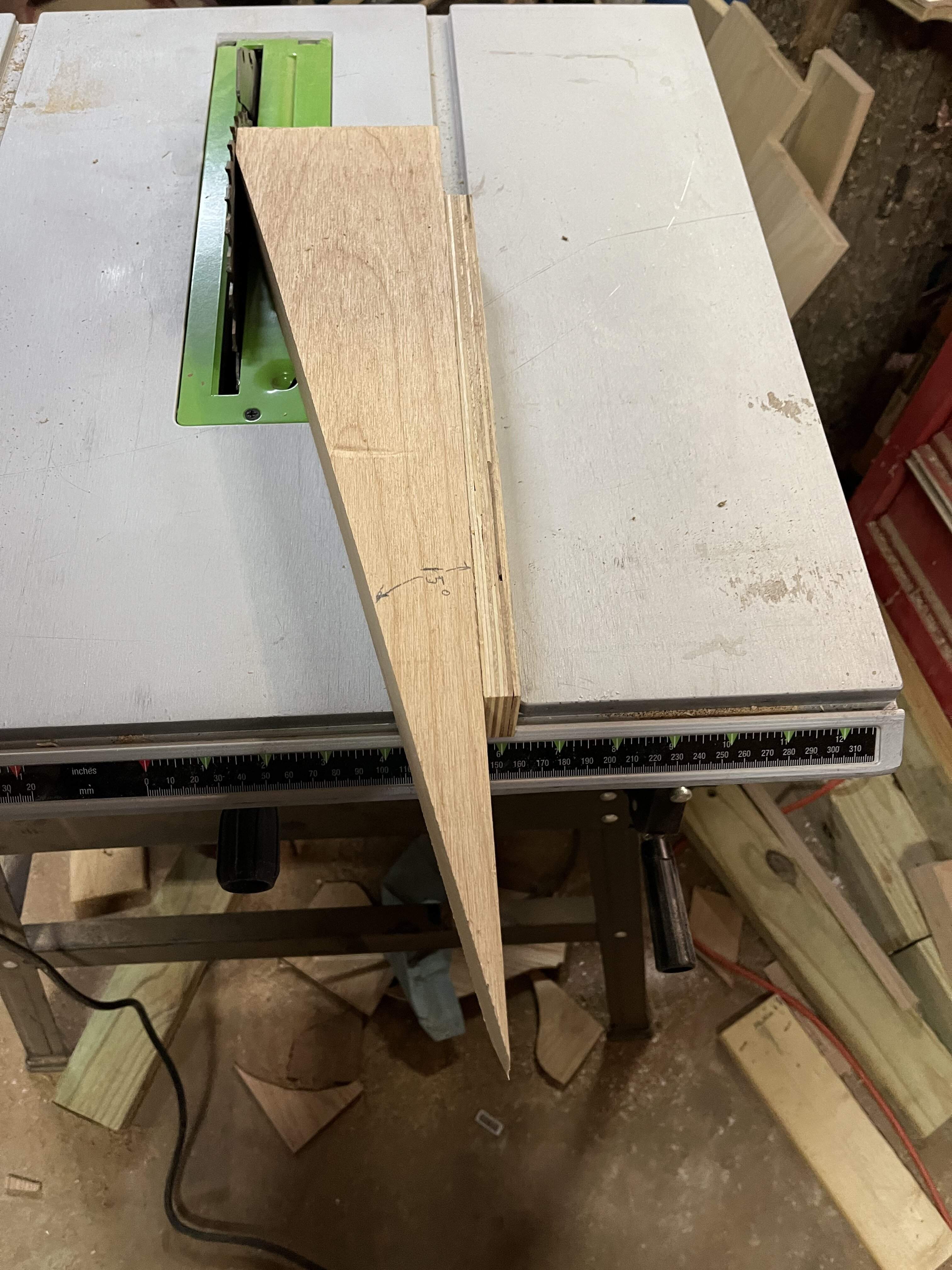
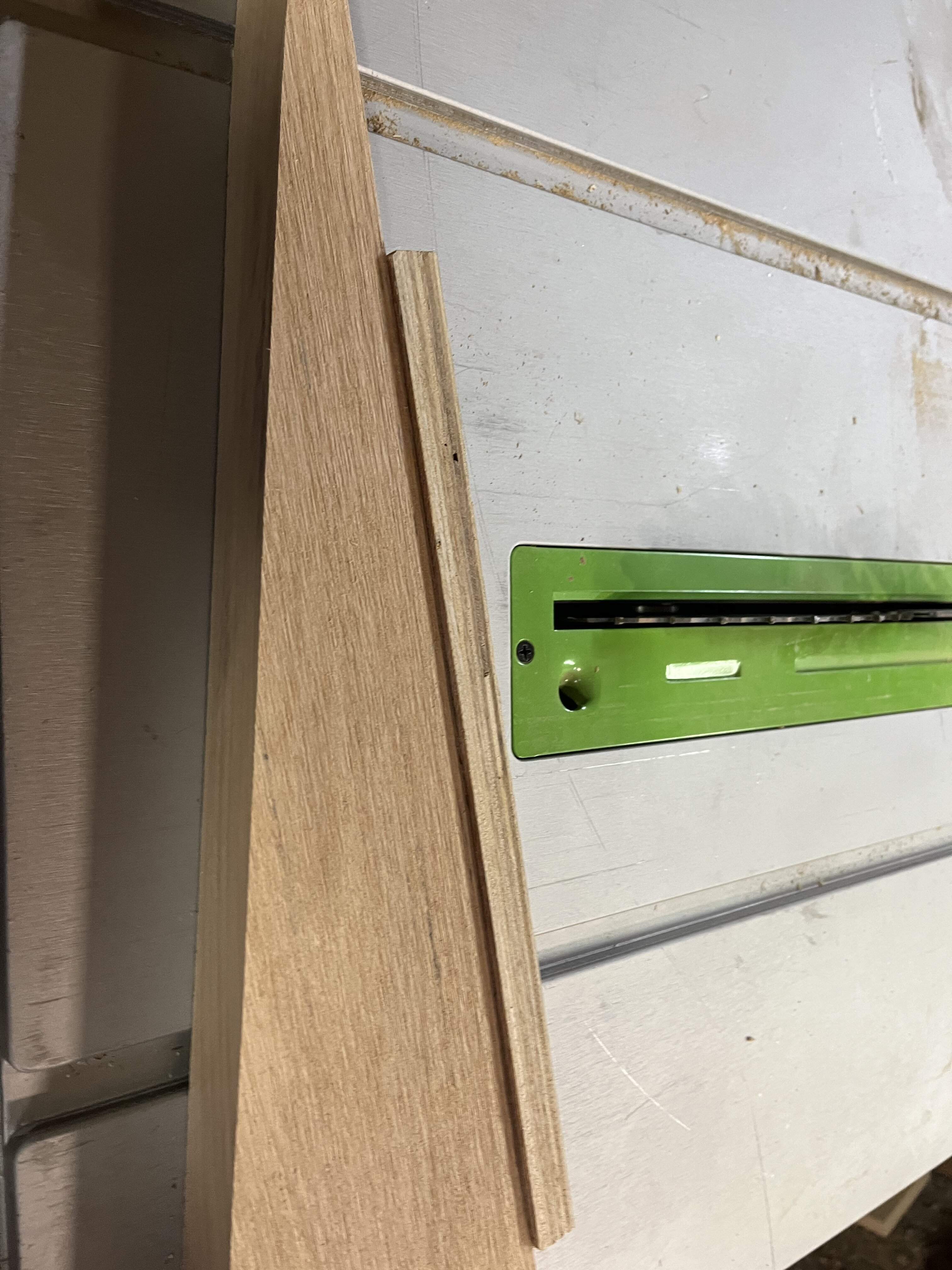
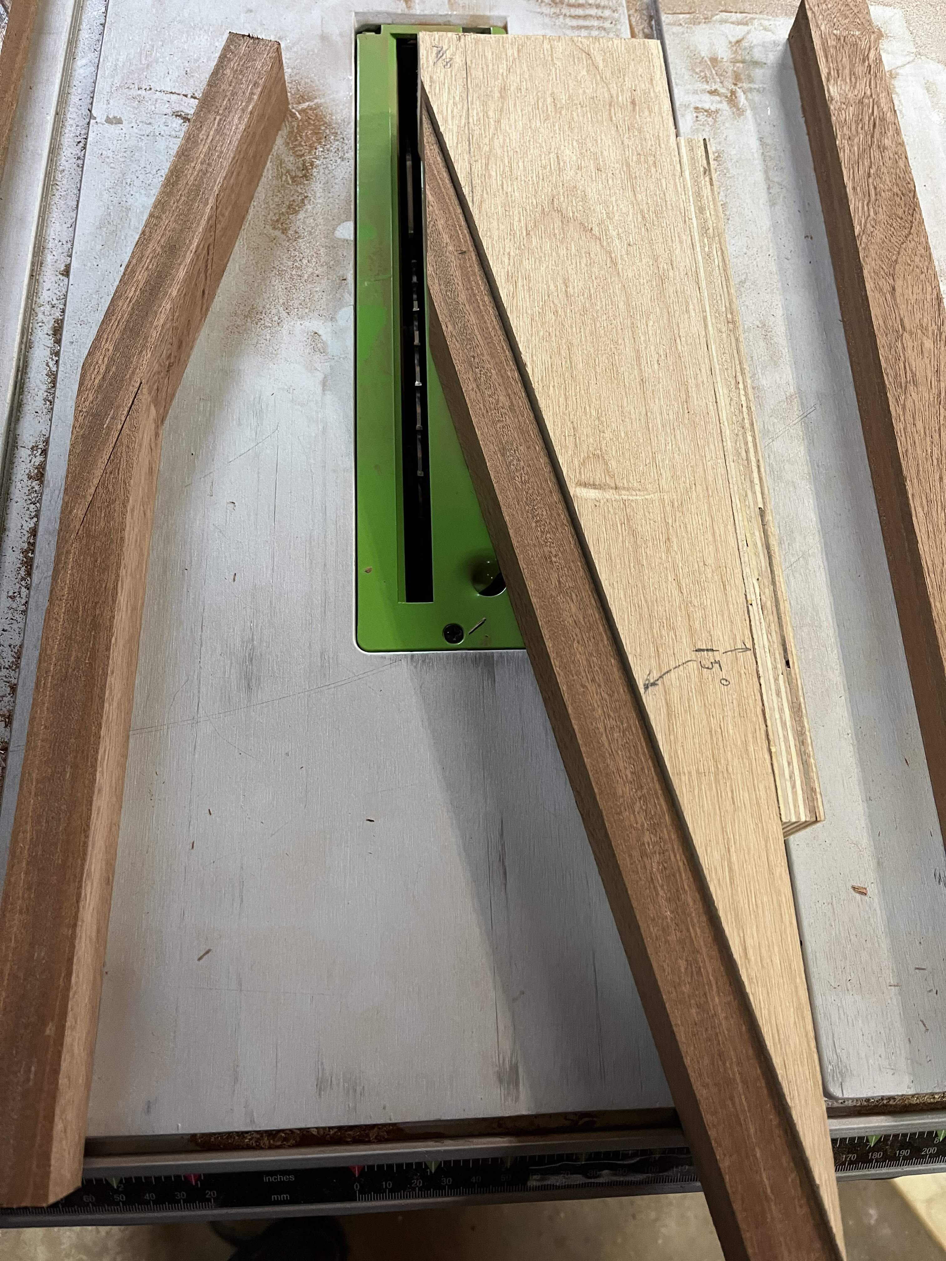
To get the fit flip the part that will become the headstock over as shown above. But this is just to check our accuracy. We don't make the actual joint until a little later.
Note that the 1-1/2" dimension is vertical for this cut, and the 7/8" dimension is horizontal.
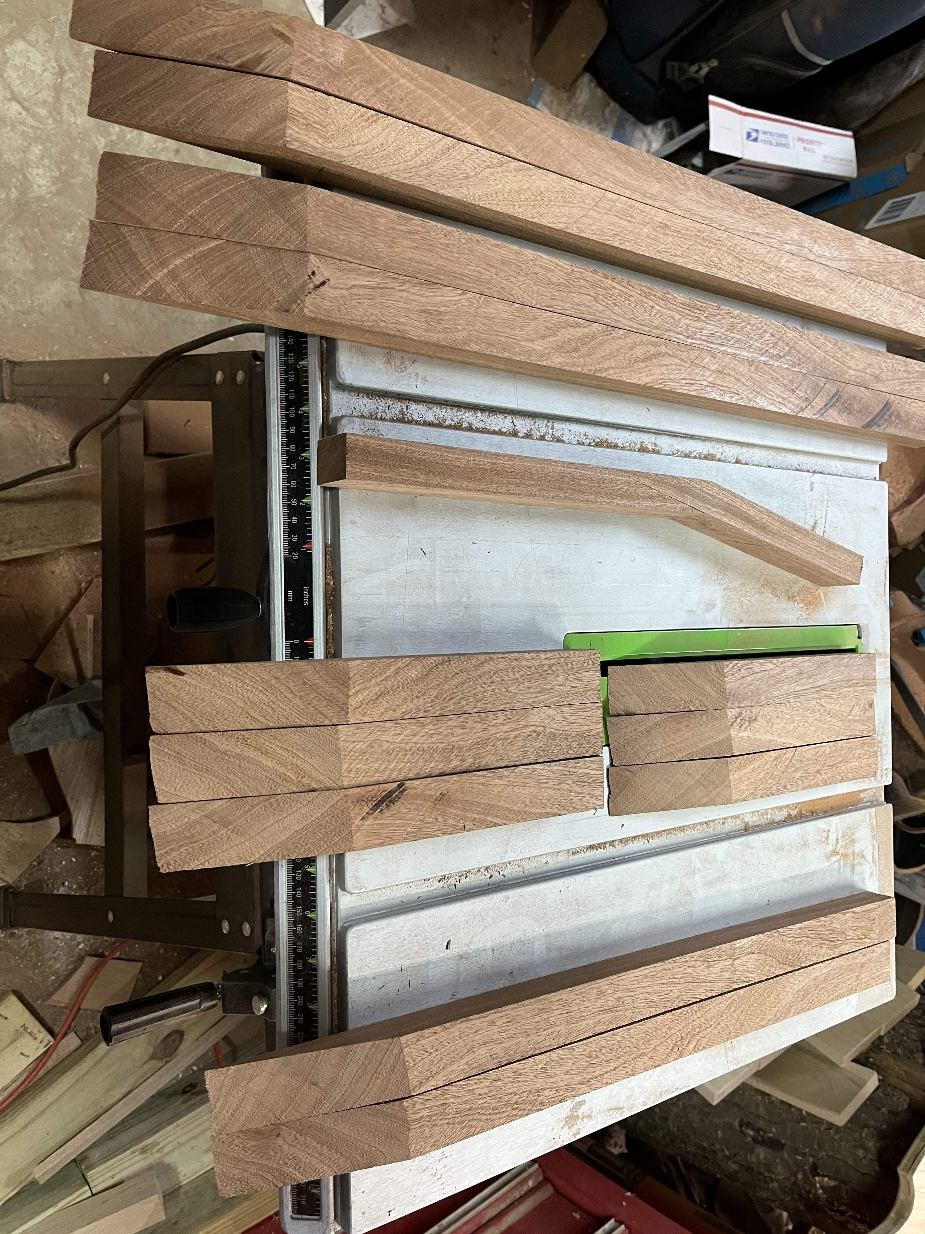
After cutting the pieces to my predetermined sizes. (2 pieces are glued side to side to make a neck blank, and 3 to make a headstock.) you can see that my one board yielded the material to make:
I have started building scarfed joint necks, mostly because i wanted to build an all Sapele bass. Well, all except the pickguard which will be Walnut. The pickguard will be inlaid, flush with the top. Why make a flush pickguard? you might ask. several reasons:
- It is a way to incorporate contrasting woods, or just give an accent.
- It allows me to have active pups and wiring without a separate hole for a battery.
- It gives access to the controls/wiring for repairs.
- It makes my instruments unique, thus more valuable.
- I just like them
my necks will be 40mm or some 38mm at the nut and 60mm at the heel. 3/4 thick with a 4" wide x 1/2" thick headstock. C shape body.
Part 1 is about how to make the scarf joint.
First, I need a couple fixtures or jigs... I will make everything from 6/4 lumber (1-1/2" thick). In this example I used a piece of sapele 7" wide by 48" long.
first jig... I need to assure that My pieces are all uniform sizes. Rather than trusting my cheap table saw fence to be consistent, and my eye to be true, I made a fence that uses the guide slot in the saw table to assure that it is always the same. the plywood fastened to the side fits down into the slot, holding the jig in place.
Now i need to cut a 15degree angle.... not an easy thing to do consistently with any normal shop tools.
Jig number 2... a way to cut 15Degree angles...
Many builders use a band saw for this, others use a miter saw.
I chose to use my table saw. Here is how I do it.
First i hand cut a piece of wood at a 15 degree angle. Then I attached a piece of 5/8" plywood to it to follow the table slot. I then hold a piece of wood against it(or attach it with double stick tape), and slide the entire assembly through the saw, jig and all. see below.
To get the fit flip the part that will become the headstock over as shown above. But this is just to check our accuracy. We don't make the actual joint until a little later.
Note that the 1-1/2" dimension is vertical for this cut, and the 7/8" dimension is horizontal.
After cutting the pieces to my predetermined sizes. (2 pieces are glued side to side to make a neck blank, and 3 to make a headstock.) you can see that my one board yielded the material to make:
- 2 full size necks. (top)
- 1 short scale neck (bottom)
- 2 headstocks (above short scale neck pieces)
- 2 pieces toward a third headstock ( middle, arranged to show how the joint is made.)
Attachments

hello everyone! remember me. my garage/shop has been too cold to work in for a while, but I am back now.
I have started building scarfed joint necks, mostly because i wanted to build an all Sapele bass. Well, all except the pickguard which will be Walnut. The pickguard will be inlaid, flush with the top. Why make a flush pickguard? you might ask. several reasons:
anyway, I digress... this post is part 1 of how this mediocre builder makes scarfed joint necks.
- It is a way to incorporate contrasting woods, or just give an accent.
- It allows me to have active pups and wiring without a separate hole for a battery.
- It gives access to the controls/wiring for repairs.
- It makes my instruments unique, thus more valuable.
- I just like them
my necks will be 40mm or some 38mm at the nut and 60mm at the heel. 3/4 thick with a 4" wide x 1/2" thick headstock. C shape body.
Part 1 is about how to make the scarf joint.
First, I need a couple fixtures or jigs... I will make everything from 6/4 lumber (1-1/2" thick). In this example I used a piece of sapele 7" wide by 48" long.
first jig... I need to assure that My pieces are all uniform sizes. Rather than trusting my cheap table saw fence to be consistent, and my eye to be true, I made a fence that uses the guide slot in the saw table to assure that it is always the same. the plywood fastened to the side fits down into the slot, holding the jig in place.
View attachment 4655473View attachment 4655474 After ripping the board 4 times i have 4 pieces of wood 7/8" x 1-1/2" x 48" and about 1/2" thick piece left over.
Now i need to cut a 15degree angle.... not an easy thing to do consistently with any normal shop tools.
Jig number 2... a way to cut 15Degree angles...
Many builders use a band saw for this, others use a miter saw.
I chose to use my table saw. Here is how I do it.
First i hand cut a piece of wood at a 15 degree angle. Then I attached a piece of 5/8" plywood to it to follow the table slot. I then hold a piece of wood against it(or attach it with double stick tape), and slide the entire assembly through the saw, jig and all. see below.
View attachment 4655471 View attachment 4655472 View attachment 4655477
To get the fit flip the part that will become the headstock over as shown above. But this is just to check our accuracy. We don't make the actual joint until a little later.
Note that the 1-1/2" dimension is vertical for this cut, and the 7/8" dimension is horizontal.
After cutting the pieces to my predetermined sizes. (2 pieces are glued side to side to make a neck blank, and 3 to make a headstock.) you can see that my one board yielded the material to make:
- 2 full size necks. (top)
- 1 short scale neck (bottom)
- 2 headstocks (above short scale neck pieces)
- 2 pieces toward a third headstock ( middle, arranged to show how the joint is made.)
View attachment 4655476
How is this mediocre???
I decided to be really silly this year, and recreate the MPC Outlaw with built in effects, only instead of using plug-in analog modules, I used an Electrosmith Daisy DSP to implement the effects mounted on a PedalPCB Terrarium board to for its signal buffers:
View attachment 4641779
The two bottom knobs are rotary encoders rather than pots, and there's a tiny 0.96" OLED display in the upper horn:
View attachment 4641780
Here's the brains of the operation:
View attachment 4641781
Still some work to do making rear covers, etc. I also plan to put a burst on it to deal with the color mismatch on the display bezel.
Interesting potion for the p-bass pups. how do those sound that close to the bridge. I would guess they would sound very clean.
Yes they sound very clean. The position came from aping the original albeit with an adjustment for the shorter scale length (32.5 vs 34). I currently have it apart, monkeying with how the controls connect without having to disassemble or de-solder if I need to work on something. I'm going to record some sound samples.Interesting potion for the p-bass pups. how do those sound that close to the bridge. I would guess they would sound very clean.
You've come a long way from your first build. I'm glad you're faithful to our little corner of mediocre builders and I'm equally glad to see you do things "differently". We all have ways to do them and there's no "perfect" way, except maybe when you have a truckload of money and can afford state-of-the-art CNC equipment. But that's just no fun.hello everyone! remember me. my garage/shop has been too cold to work in for a while, but I am back now.
I have started building scarfed joint necks, mostly because i wanted to build an all Sapele bass. Well, all except the pickguard which will be Walnut. The pickguard will be inlaid, flush with the top. Why make a flush pickguard? you might ask. several reasons:
anyway, I digress... this post is part 1 of how this mediocre builder makes scarfed joint necks.
- It is a way to incorporate contrasting woods, or just give an accent.
- It allows me to have active pups and wiring without a separate hole for a battery.
- It gives access to the controls/wiring for repairs.
- It makes my instruments unique, thus more valuable.
- I just like them
my necks will be 40mm or some 38mm at the nut and 60mm at the heel. 3/4 thick with a 4" wide x 1/2" thick headstock. C shape body.
Part 1 is about how to make the scarf joint.
First, I need a couple fixtures or jigs... I will make everything from 6/4 lumber (1-1/2" thick). In this example I used a piece of sapele 7" wide by 48" long.
first jig... I need to assure that My pieces are all uniform sizes. Rather than trusting my cheap table saw fence to be consistent, and my eye to be true, I made a fence that uses the guide slot in the saw table to assure that it is always the same. the plywood fastened to the side fits down into the slot, holding the jig in place.
View attachment 4655473View attachment 4655474 After ripping the board 4 times i have 4 pieces of wood 7/8" x 1-1/2" x 48" and about 1/2" thick piece left over.
Now i need to cut a 15degree angle.... not an easy thing to do consistently with any normal shop tools.
Jig number 2... a way to cut 15Degree angles...
Many builders use a band saw for this, others use a miter saw.
I chose to use my table saw. Here is how I do it.
First i hand cut a piece of wood at a 15 degree angle. Then I attached a piece of 5/8" plywood to it to follow the table slot. I then hold a piece of wood against it(or attach it with double stick tape), and slide the entire assembly through the saw, jig and all. see below.
View attachment 4655471 View attachment 4655472 View attachment 4655477
To get the fit flip the part that will become the headstock over as shown above. But this is just to check our accuracy. We don't make the actual joint until a little later.
Note that the 1-1/2" dimension is vertical for this cut, and the 7/8" dimension is horizontal.
After cutting the pieces to my predetermined sizes. (2 pieces are glued side to side to make a neck blank, and 3 to make a headstock.) you can see that my one board yielded the material to make:
- 2 full size necks. (top)
- 1 short scale neck (bottom)
- 2 headstocks (above short scale neck pieces)
- 2 pieces toward a third headstock ( middle, arranged to show how the joint is made.)
View attachment 4655476
I hope somewhere this summer I can join in again with some of my paused builds. For now, I'm dealing with a 100+ year old bathroom floor which I cannot replace because I can't afford it, so yeah, I know what "doing things differently" means.
If one method fails, don't nag, sit down and think how to do it in another way.
Cheers and keep up your good spirit!
I glued the pieces together then smoothed them all with a jointer. the neck is going well.
I do have problem though...
I have too damn many ideas and not enough time (and money) to pursue them all.
I talked about the recessed pickguards already.
but right now, i am focused on something more revolutionary than my floating top bass.
I am planning to build a bass I designed, that will have no visible pickups and no controls of any kind on the body.
just pure wood from the neck to the bridge.
How?
I have already designed a wiring box and all the wiring for an active P-J bass with a blend pot and 3 band equalizer.
I am also looking into a couple options for passive remotes.
To avoid any voltage, drop i will be using 20ga and 18 gauge wires instead of 24-28ga.
Now I am getting excited.... in the process of building the first couple remote boxes.
I do have problem though...
I have too damn many ideas and not enough time (and money) to pursue them all.
I talked about the recessed pickguards already.
but right now, i am focused on something more revolutionary than my floating top bass.
I am planning to build a bass I designed, that will have no visible pickups and no controls of any kind on the body.
just pure wood from the neck to the bridge.
How?
- I will use 4 Graphtec Ghost pickups mounted as part of a Hipshot KickAss Bridge.
- they will be wired to a signal combiner under the bridge.
- from there they will be wired directly to a 3.5mm TRRS receptacle.
- a 3.5mm TRRS cable will carry the signal to a remote box also equipped with a 3.5mm TRRS receptacle.
- the box will contain all of the controls and have a standard 1/4" mono output to the amp.
I have already designed a wiring box and all the wiring for an active P-J bass with a blend pot and 3 band equalizer.
I am also looking into a couple options for passive remotes.
To avoid any voltage, drop i will be using 20ga and 18 gauge wires instead of 24-28ga.
Now I am getting excited.... in the process of building the first couple remote boxes.
Last edited:

Make sure the bass to control box is as short as possible and low capacitance an the C will affect the frequency response of the piezos. Wire resistance is less important here as it's a high impedance system.How?
- I will use 4 Graphtec Ghost pickups mounted as part of a Hipshot KickAss Bridge.
- they will be wired to a signal combiner under the bridge.
- from there they will be wired directly to a 3.5mm TRRS receptacle.
- a 3.5mm TRRS cable will carry the signal to a remote box also equipped with a 3.5mm TRRS receptacle.
- the box will contain all of the controls and have a standard 1/4" mono output to the amp.
Make sure the bass to control box is as short as possible and low capacitance an the C will affect the frequency response of the piezos. Wire resistance is less important here as it's a high impedance system.
I have been considering this. I plan to start with a 6' to 10' lead and see how that works. If i need to shorten it, i have an idea for a leather teather to hold the box attached to the bass by a large snap. I hope to not need to go there because it defeats the whole reason for the concept. an 18vpower supply will power the system. But as you say the potential for a problem is from the pickups to the box which with a piezo system the added power won't help.
The version for an active P-J magnetic pickup combo will be helped because the 18v power is fed into the pickups.
I am hoping for the best with the piezo, but it is new territory for me.
I have been trying to find optical pickups (light-wave) to mount in the bridge but it seems they are proprietary still. The only way to get those pickups is on a guitar built by the manufacturer. Nobody sells just the pickups. At least, not the ones that mount in the bridge.
I have been toying with the idea of making my own optical pickups by modifying 3mm "horseshoe" optical proximity sensors with mA output.
I am pretty sure i could do it using a PLC. unfortunately PLCs are not that small yet.
Last edited:
I might have jumped in too early. It's a while since I looked at these in detail, but does the combiner board actively buffer the piezos? If so, ignore me as I thought they were unbufferred and I don't have time to read through the manual again at the moment, but I will later, post meeting.
I might have jumped in too early. It's a while since I looked at these in detail, but does the combiner board actively buffer the piezos? If so, ignore me as I thought they were unbufferred and I don't have time to read through the manual again at the moment, but I will later, post meeting.
I am somewhat hopeful because there is a wiring option using these pickups as passive pickups. It recommends adding a powered gain pot to do it, which i have never tried, but i might get the itch to try. But i would probably do it as a static gain rather than a pot. There is an available conductor in the TRRS cabling to bring power to the body for something like this.
I never imagined when i started to build basses that they would challenge my electrical engineering capabilities. lololololol
Last edited:
Not so keen on that idea myself.I am somewhat hopeful because there is a wiring option using these pickups as passive pickups.
Then that sounds like there's a buffer.It recommends adding a powered gain pot to do it
Reason I'm commenting is I'd like to do the hex out version on a bass VI type build myself later.
Then that sounds like there's a buffer.
Reason I'm commenting is I'd like to do the hex out version on a bass VI type build myself later.
I will share my experiences, both good and bad in the hope of mutual benefit.
Be aware of using good decoupling and filtering when using external power as the power wires tend to pickup transient distortions easily.I am somewhat hopeful because there is a wiring option using these pickups as passive pickups. It recommends adding a powered gain pot to do it, which i have never tried, but i might get the itch to try. But i would probably do it as a static gain rather than a pot. There is an available conductor in the TRRS cabling to bring power to the body for something like this.
I never imagined when i started to build basses that they would challenge my electrical engineering capabilities. lololololol
I glued the pieces together then smoothed them all with a jointer. the neck is going well.
I do have problem though...
I have too damn many ideas and not enough time (and money) to pursue them all.
I talked about the recessed pickguards already.
but right now, i am focused on something more revolutionary than my floating top bass.
I am planning to build a bass I designed, that will have no visible pickups and no controls of any kind on the body.
just pure wood from the neck to the bridge.
How?
This is going to be the prototype for an entire line of basses. That is, using a remote box for the electronics with a TRRS interface. this will include an option (for about $200 extra) to include a 13pin midi output to interface for a fully synthesized bass. A compatible Rolland GR-55 synthesizer runs about $900. Expensive, but it would yield a fully synthesized bass with more voicings and affects than I can count.
- I will use 4 Graphtec Ghost pickups mounted as part of a Hipshot KickAss Bridge.
- they will be wired to a signal combiner under the bridge.
- from there they will be wired directly to a 3.5mm TRRS receptacle.
- a 3.5mm TRRS cable will carry the signal to a remote box also equipped with a 3.5mm TRRS receptacle.
- the box will contain all of the controls and have a standard 1/4" mono output to the amp.
I have already designed a wiring box and all the wiring for an active P-J bass with a blend pot and 3 band equalizer.
I am also looking into a couple options for passive remotes.
To avoid any voltage, drop i will be using 20ga and 18 gauge wires instead of 24-28ga.
Now I am getting excited.... in the process of building the first couple remote boxes.
Rick Turner does something similar but there are controls on the body. Piezo pickup.
[Invalid or Expired Link Removed]
Looking forward to seeing something!
Rick Turner does something similar but there are controls on the body. Piezo pickup.
[Invalid or Expired Link Removed]
Looking forward to seeing something!
Yes i have seen a few guitars with piezo pickups in the bridge, but none with no controls on the body.
that was the whole innovative point of the design.
I might have a solution. but like MirandM said, I will have to build and test it before I know if i have it.
Potential solution.....
- I move the Acousti-Phonic preamp to the cavity under the bridge. (It is only about 1-1/4" x 1-5/8".)
- reduce the power supply to 9v (maybe, help me with this, i need advice)
- locate the battery, volume pot, mid/dark switch, and output jack in the remote box.
- use two TRRS cables (held together with tiny cable ties every few inches or a cable wrap) to connect them. One cable with male ends, and one with female ends, so they cannot get crossed.
- better idea = use an eight conductor CAT-6 RJ45 cable to connect them. I would just have to trust the end user to never try to plug it into a computer network, since the pinouts would not be standard. I would include a warning, but.......
- As a last resort I could make a 9-pin D connector cable to connect them. but that carries the same problem as the RJ45. On the plus side i could use larger wire, which, not being between the pickups and the preamp might possibly improve the signal integrity.
Last edited:
Go with a 9-pin DIN connector -- not likely to be confused with anything else. As for the 9-V vs 18-V, try it. Worst case you could go with a charge pump board like the MadBean RoadRage to increase the voltage to 18 if needed. The DSP that I'm using in the Outlaw bass is running the analog at 5 V and it sounds fine.


