• TalkBass has been independent since 1998. Add your voice.
    Create a free account to reply to discussions, view embedded media, and browse with fewer display ads.
    Join freeLog in
    Want zero display ads or expanded classifieds tools? Compare plans.

What's On Your Workbench?

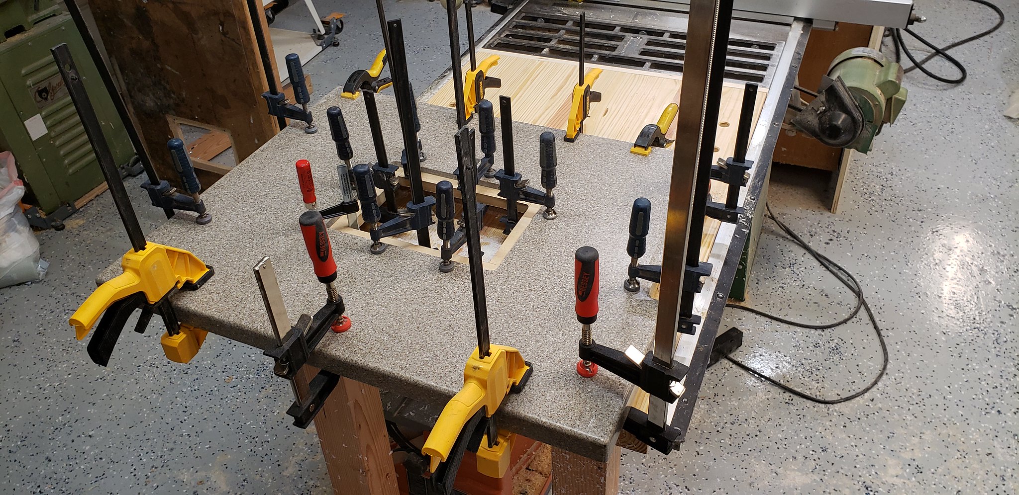
Today is a very "Inception"-like day. On my bench is...another bench. I'm making a new bench to go on my table saw wing. The single layer MDF with 2x4 frame just isn't doing it any more, so I am making a traditional woodworking bench sized to fit:

Invalid Link Removed


Just about ready to mount, just need some 3/4 dowel, a few 1/2" square nuts, and the commitment to getting my router table finished, as my old table doubled as my router table. I will then drill some dog holes in the top, another coat of oil, and it should be ready to rock.
 
Streamer project update:
IMG_5076.JPG

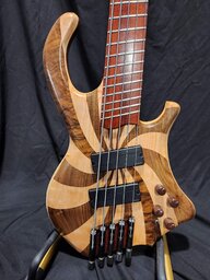
The top is roughed out, but needs quite a bit of fine tuning still.
IMG_5073.JPG

Started carving the back. I routed a 5cm wide channel down the middle to the approximate depth first. These violin maker's planes do a really good job shaping the curved surfaces.
IMG_5078.JPG

And after a couple of hours with the small planes (and a good sized blister on my thumb) it looks like this. It's about 1800 grams now and the roundovers will remove a bit more, so it will be a very lightweight body.
 
I need to do this, I use my table saw wing as a router table, it came with my tablesaw when I bought it. It's made from 50 year old formica and has a sag in the middle. I have to adjust the depth of cut on my router to account for the sag. I've gotten pretty good at that, but it's not good!

Yeah, I've decided a separate router table will work best for my setup. I got the dog holes all drilled and countersunk with more finish on. It's now ready to assemble and install, which is what I'm hoping to do after work today.
 
Yeah, I've decided a separate router table will work best for my setup. I got the dog holes all drilled and countersunk with more finish on. It's now ready to assemble and install, which is what I'm hoping to do after work today.
I just don't have enough room for a dedicated router table. Right now I have to crawl under the extension to adjust the router, I hate that but I can still do it while I'm young(ish) :-D
 
  • Like
Reactions: TerribleTim68
No excuse, either way!

PgsQ2CP.jpg


This is with the pickups switched by in. The pots and switch give a sense of scale.
I feel like I know why, but it’s not a good reason. Seems like they can mount everything, holding onto all the wire ends and then clipping them together.. so each individual component needs enough wire to reach ‘out’ of the guitar to clip into the next. Pretty elaborate plan to make it... I guess easier to throw these together
 
  • Like
Reactions: Axstar
Got the overall design for the guitars finished. I'm actually taking my time and building a full set of templates for each part this time so it'll be repeatable. Something I've never bothered to do before! I am looking forward to being able to just slap templates on some wood and buzz out an instrument, instead of having to pause, measure, design, calculate etc at every step.
IMG_20191101_073141.jpg
 
Ok, so this isn't directly related to bass building, but I figured I's share in case some found it useful.

I came across some RGB LEDs that are adressable and small enough to be used as side markers. They are called SK9822-2020. They are 2x2mm, so they will almost fit into the circle of a 3/32" side dot.
IMG_2288.JPG

This is a kind of adressable LED that uses a separate clock signal which make them easier to control, but you will need an extra wire. There is a similar version (SK6812-2020) available that only needs data, but require fairly strictly timed data signals.
IMG_2277.JPG

Since there is a slight offset between the red, green and blue LED dies the LED will need some kind of diffuser to prevent the slight rainbow pattern of the raw led.
IMG_2282.JPG


The brightness is pretty impressive for such a tiny RGB LED. The picture above was taken under a relatively bright desk light.

The two drawbacks of these are that they are a bit tricky to solder to wires, and that they need to be (in my opinion) fitted in a way that makes it possible to replace broken LEDs. Electronics do sometimes fail. if these are glued into a neck they will be next to impossible to replace.

Also, if you drop one on the floor it will become vacuum cleaner food. Guess how i know... :meh:
 
Ok, so this isn't directly related to bass building, but I figured I's share in case some found it useful.

I came across some RGB LEDs that are adressable and small enough to be used as side markers. They are called SK9822-2020. They are 2x2mm, so they will almost fit into the circle of a 3/32" side dot.
View attachment 3590155
This is a kind of adressable LED that uses a separate clock signal which make them easier to control, but you will need an extra wire. There is a similar version (SK6812-2020) available that only needs data, but require fairly strictly timed data signals.
View attachment 3590156
Since there is a slight offset between the red, green and blue LED dies the LED will need some kind of diffuser to prevent the slight rainbow pattern of the raw led.
View attachment 3590158

The brightness is pretty impressive for such a tiny RGB LED. The picture above was taken under a relatively bright desk light.

The two drawbacks of these are that they are a bit tricky to solder to wires, and that they need to be (in my opinion) fitted in a way that makes it possible to replace broken LEDs. Electronics do sometimes fail. if these are glued into a neck they will be next to impossible to replace.

Also, if you drop one on the floor it will become vacuum cleaner food. Guess how i know... :meh:

Each tiny LED square has three wires? So 9x3=27 (on a standard 20 fret neck) wires to connect under the fb? And what do those wires attach to for power?
 
fitted in a way that makes it possible to replace broken LEDs

I've done a lot of embedded electronics work but I can't quite imagine how you would accomplish an LED side marker that was easily replaceable. Did you have something in mind? I guess you could come up with a way to include slack in the wiring - maybe a void in the neck behind the LED that let you tuck a fold of wiring in there - and then just plan on drilling out the bad part, pulling the extra wiring out and soldering on a new one, then gluing it in?
 
Each tiny LED square has three wires? So 9x3=27 (on a standard 20 fret neck) wires to connect under the fb? And what do those wires attach to for power?

it's 6 wires per LED. Power, ground, data in, clock in, data out, clock out. In the picture I posted there are 4 wires, but the black one isn't visible. I didn't bother wiring up the outputs as I was running only one LED. The beauty of these is that you don't need separate wires for each led. The first LED sends data to the next. The power is shared so you only run 4 wires. One must be careful to run thick enough power wires to prevent voltage drop if the LEDs are run at full power, but a neck is fairly short and doesn't need many points of light. Oh, and the LEDs need 5 volts to run, but most lots of microcontrollers do as well, so they can share voltage regulators. A small Arduino board would work, but maybe not at full power. If more power is needed there are lots of cheap regulators that would work. :)

I've done a lot of embedded electronics work but I can't quite imagine how you would accomplish an LED side marker that was easily replaceable. Did you have something in mind? I guess you could come up with a way to include slack in the wiring - maybe a void in the neck behind the LED that let you tuck a fold of wiring in there - and then just plan on drilling out the bad part, pulling the extra wiring out and soldering on a new one, then gluing it in?

I have an idea, but haven't tested anything in practice. My idea is to make a very narrow PCB the same length as the fretboard. The dots will be clear/frosted acrylic that serve as a light pipe to the PCB that will sit in a channel routed into the neck or fretboard. The routing will be open at one end where the entire PCB can be pulled out. Basically the same principle as a dual action truss rod.
 
On my bench, chairs.
I am trying to make a living as a woodwright. All my commissions so far have been for furniture (build/repair/refinish) so, gotta do what pays the bills. :D

I have built instruments years ago and I really want to do so again. I have stocked up with quite a few parts and hardware over the intervening years so I will get to it, just have to shoehorn it in between paying work. The upcoming Winter Build off is very enticing, not sure I can enter, but maybe. :unsure: