

Enjoy the benefits of a premium membership!
Upgrade Account
-
TalkBass has been independent since 1998. Add your voice.
Create a free account to reply to discussions, view embedded media, and browse with fewer display ads.
Join free Log in
Want zero display ads or expanded classifieds tools? Compare plans.
You are using an out of date browser. It may not display this or other websites correctly.
You should upgrade or use an alternative browser.
You should upgrade or use an alternative browser.
Winter build off 2022 MPUrker
- Thread starter MPU
- Start date
More options
Who Replied?

Thanks. How do you like this guitar I'm building? This one is a guitar, not a bass.
Ummm…. I was distracted by the awesomeness of it all and was, possibly, in a religious fervor.


RToday I drilled locating pins under the fretboard. I needed to make sure the fretboard positions the same every time.

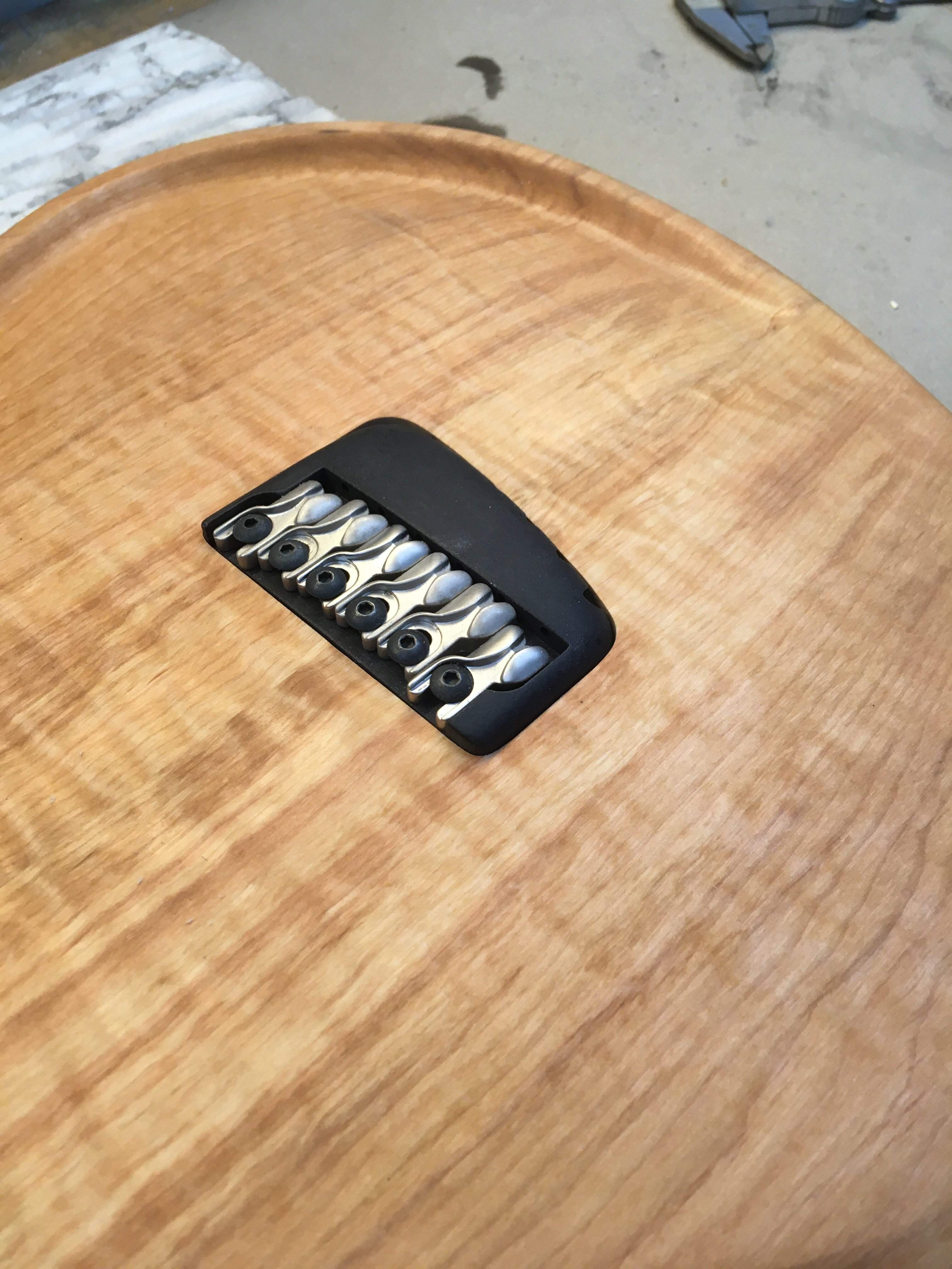
Fretboard position was needed for positioning the bridge. I taped the top with masking tape, drew the string paths and centerline to the top and after countless measurings I hot melt glued the template on the correct place. A few 3mm routing steps and the bridge cavity is routed.
Last thing today was another level sanding for the back and a coat of epoxy. One more coat later today or tomorrow morning.
I’m waiting for the fretwire and pickups, I have all the other parts already. I guess next I’m starting to rout the control cavity.
Fretboard position was needed for positioning the bridge. I taped the top with masking tape, drew the string paths and centerline to the top and after countless measurings I hot melt glued the template on the correct place. A few 3mm routing steps and the bridge cavity is routed.
Last thing today was another level sanding for the back and a coat of epoxy. One more coat later today or tomorrow morning.
I’m waiting for the fretwire and pickups, I have all the other parts already. I guess next I’m starting to rout the control cavity.
@MPU
Did you use a template to cut the bridge recess? Looks like a CNC cut! I'd screw that up for sure freehanding it.
Did you use a template to cut the bridge recess? Looks like a CNC cut! I'd screw that up for sure freehanding it.
Yes, I used a template. I don’t freehand anything except thickness routing in router sled. Templates can be very crude and temporary one offs but I use them always.@MPU
Did you use a template to cut the bridge recess? Looks like a CNC cut! I'd screw that up for sure freehanding it.
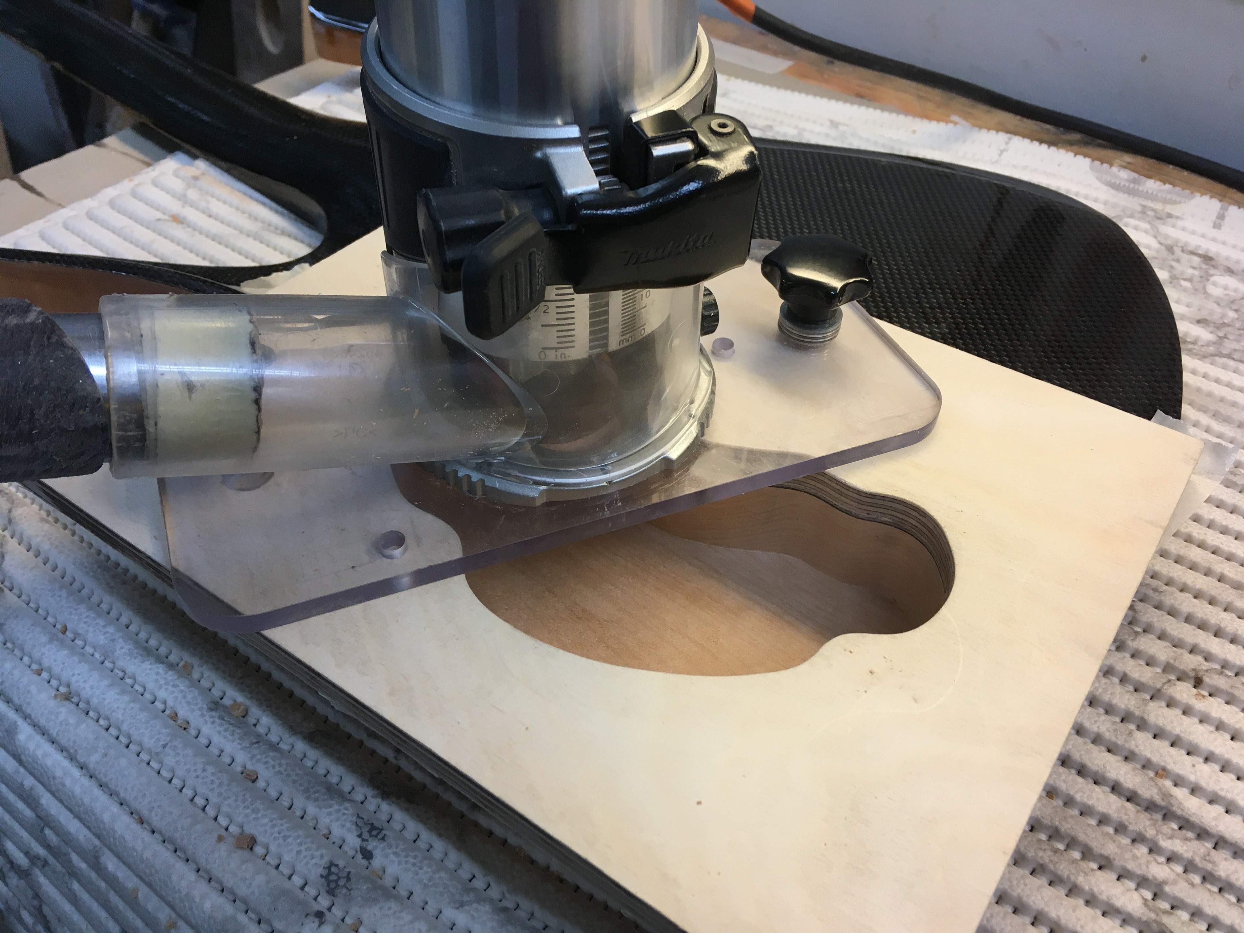
Today started with a trip to local hardware store where I bought some plywood, dust masks and red Mirka scuffing pads. Then it was time to make a template for control cavity. I taped the rear of the guitar with masking tape, used a pic or Fly to mark the pot positions and drew the cavity to match those locations. Then I peeled the tape off the back and taped it to a piece of plywood. I used coping saw and sanding drum to make the template. Template is held with the Trick.
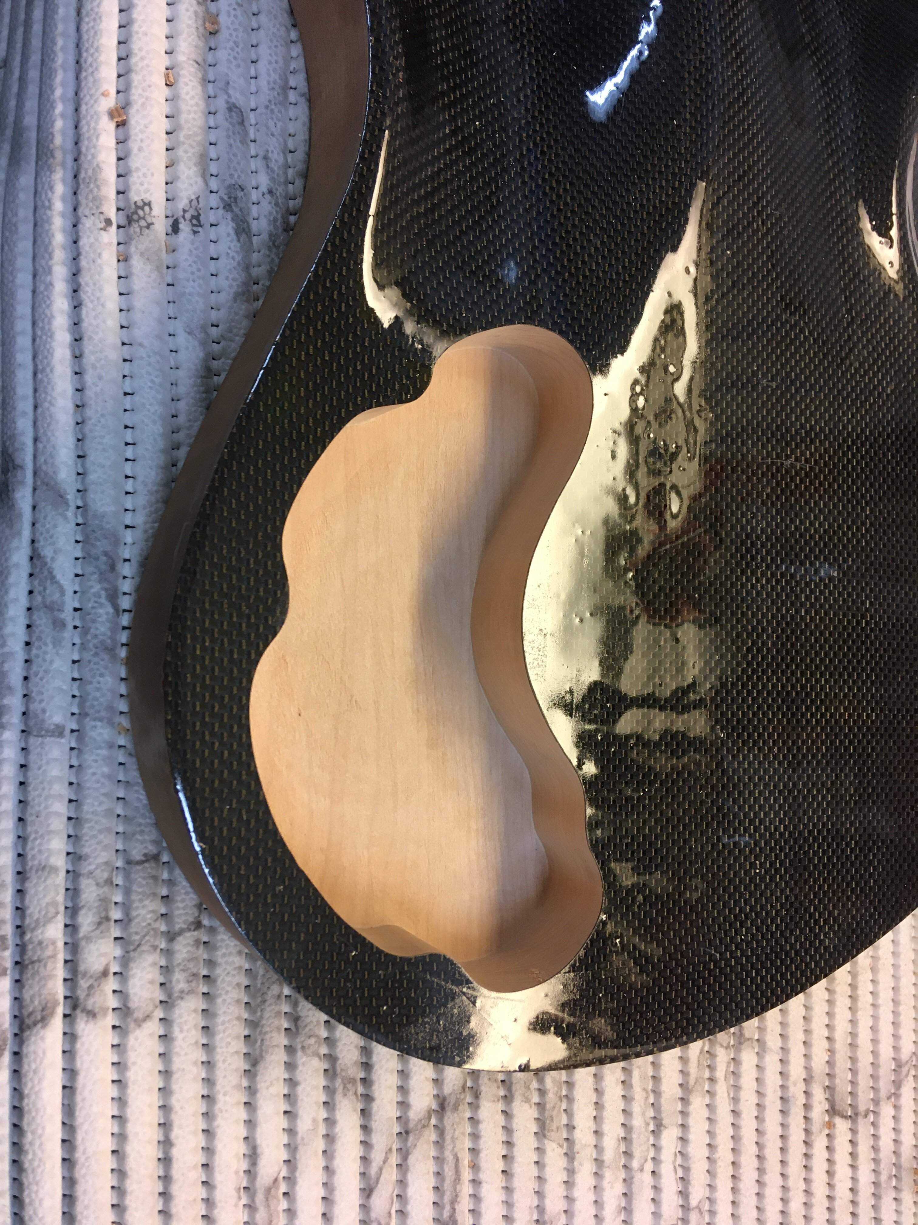
And once again, a filler coat of epoxy. I’m having a bit of a problem with fisheyes on the epoxy coats. I’m scuffing and washing the amine blush away with warn soapy water and scuffing pad, cleaning the scuffed epoxy with IPA and still there’s some fisheyes. I hope this coat has none, I have to go and check in a few moments. I soaked some epoxy in the control cawity walls as well. That prevents water swelling the alder when wet sanding the epoxy and clearcoat later on.
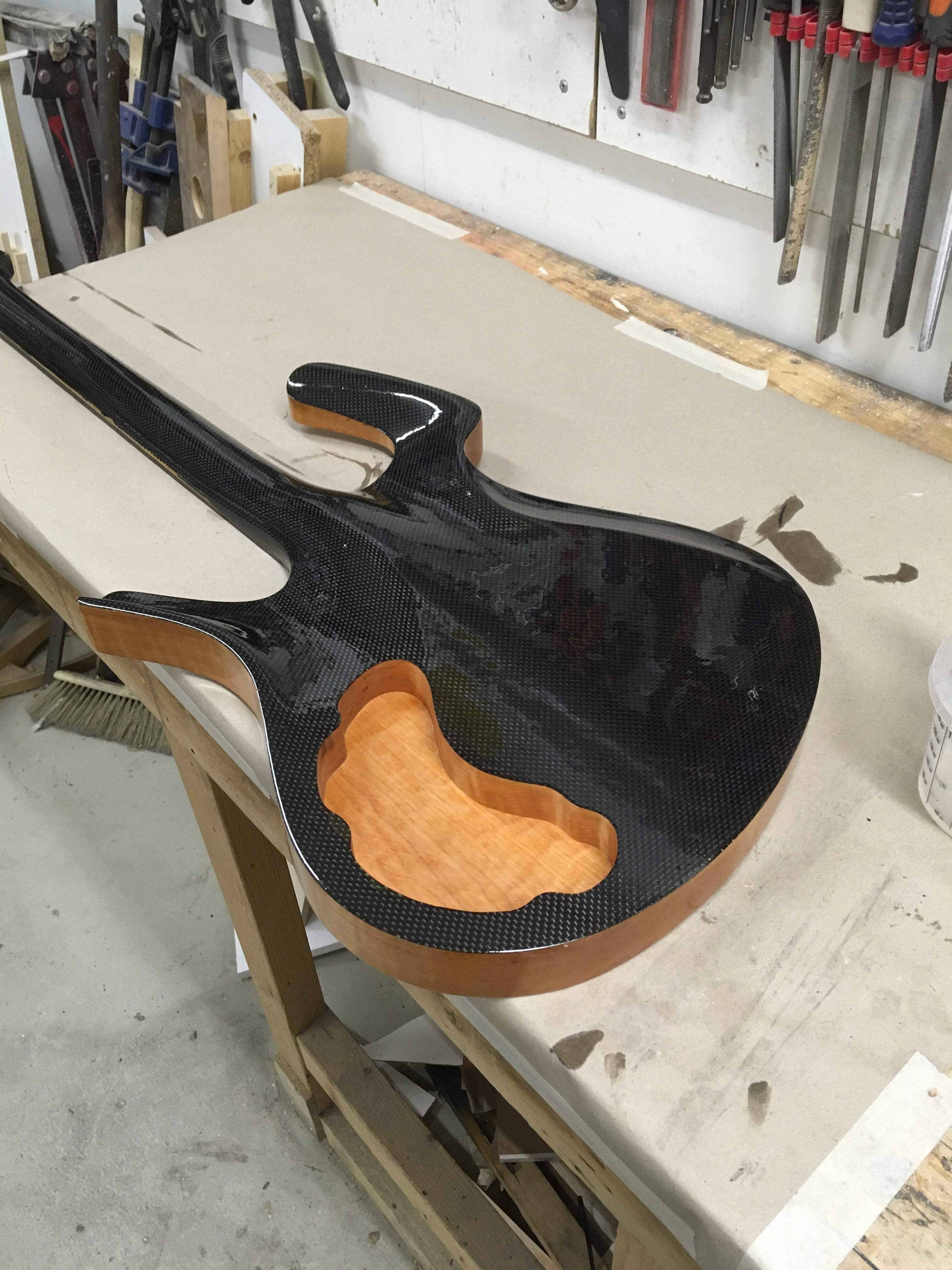
And once again, a filler coat of epoxy. I’m having a bit of a problem with fisheyes on the epoxy coats. I’m scuffing and washing the amine blush away with warn soapy water and scuffing pad, cleaning the scuffed epoxy with IPA and still there’s some fisheyes. I hope this coat has none, I have to go and check in a few moments. I soaked some epoxy in the control cawity walls as well. That prevents water swelling the alder when wet sanding the epoxy and clearcoat later on.
This is master level craftsman stuff, here. Wow.
I've always wondered - does that CF weave work as a paintable surface? Its black color and texture certainly is a distinctive and desirable look, but I always thought the curves and pattern might lend itself well to a lighter pearlescent color, or that color flip-flop paint. That flip-flop paint is pretty gaudy, but on a smaller application of this CF material, might look really cool.
I've always wondered - does that CF weave work as a paintable surface? Its black color and texture certainly is a distinctive and desirable look, but I always thought the curves and pattern might lend itself well to a lighter pearlescent color, or that color flip-flop paint. That flip-flop paint is pretty gaudy, but on a smaller application of this CF material, might look really cool.

You can, but CF has its own distinctive look (that changes with movement in a distinctive way) which is part of its appeal when used "exposed." As such, not a likely choice unless it's in a purely functional role, where it's often not visible in the first place.This is master level craftsman stuff, here. Wow.
I've always wondered - does that CF weave work as a paintable surface? Its black color and texture certainly is a distinctive and desirable look, but I always thought the curves and pattern might lend itself well to a lighter pearlescent color, or that color flip-flop paint. That flip-flop paint is pretty gaudy, but on a smaller application of this CF material, might look really cool.
If you want the "unfilled woven fabric texture + paint," fiberglass is a lot less expensive and would work as well. If you are painting over it fully filled, might as well just use poplar unless it's serving structural needs.
Last edited:
Carbon fiber is just like any other composite. You can paint it as well as clearcoat it. It can be used as structural part, visual part or both. I use it as both on this one. It takes quite a bit more work than purely structural, especially when working without molds.
Glass fiber cloth may give the same texture but not the same strength. It will strengthen the structure anyway.
Glass fiber cloth may give the same texture but not the same strength. It will strengthen the structure anyway.
Last edited:

Can you paint or color the fibers before they are covered in epoxy, or clear coat?
Or buy colored carbon fiber weave?
Or is it always and only black?
Or buy colored carbon fiber weave?
Or is it always and only black?
You can buy coloured hybrid cloths.Can you paint or color the fibers before they are covered in epoxy, or clear coat?
Or buy colored carbon fiber weave?
Or is it always and only black?
Some fine sanding to do on the contours but getting very close. Sanded to 120 grit and wetted with IPA. I really love this kind of carving. Alder carves nicely with very sharp tools.
View attachment 4548993
Wait, you wetted it with beer to see how it would look?!
Well played sir, well played.
I always think of a nice frosty glass of india pale ale when I read that too, but I don't think I'd like a nice frosty glass of isopropyl alcohol. 
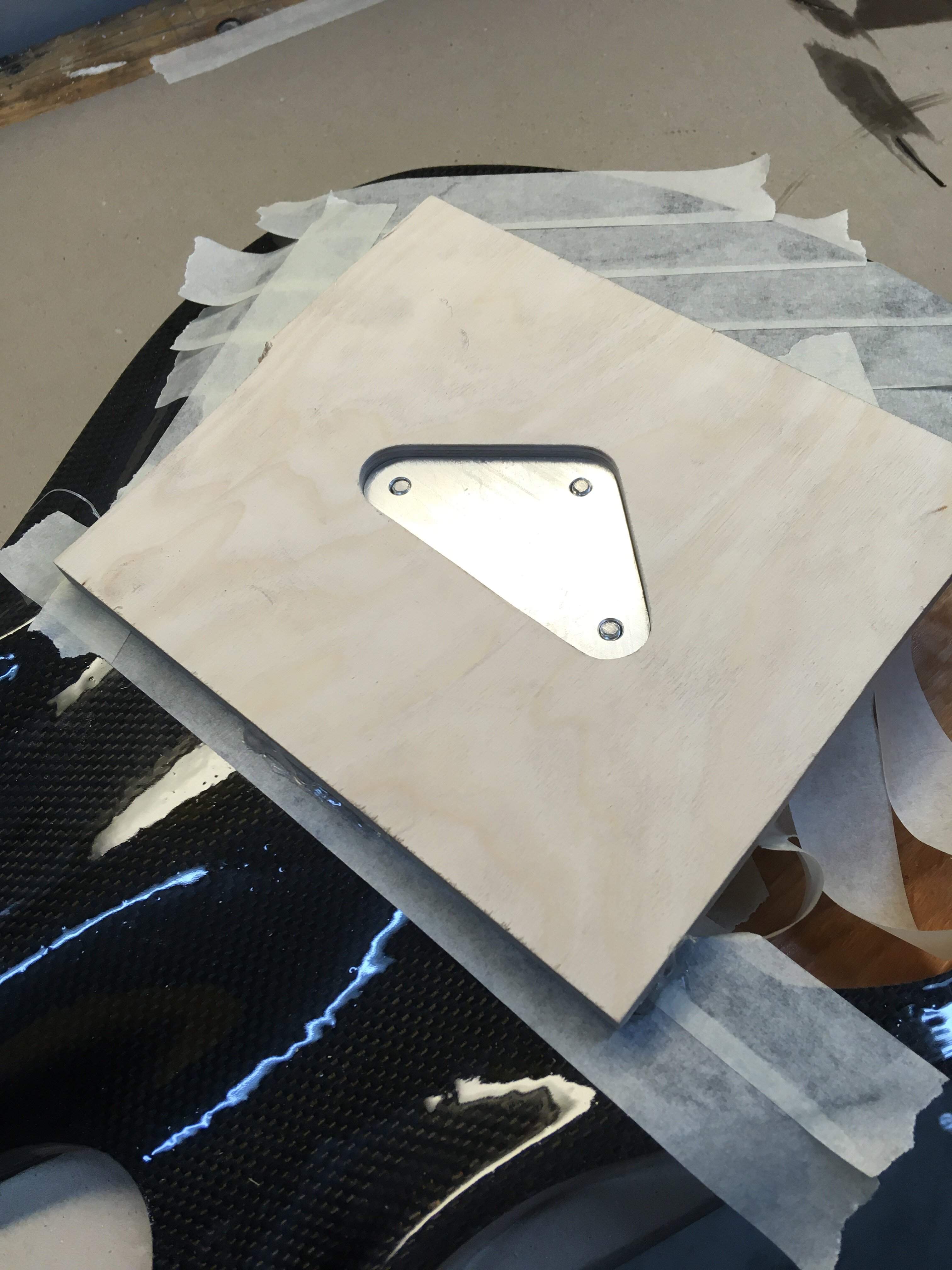
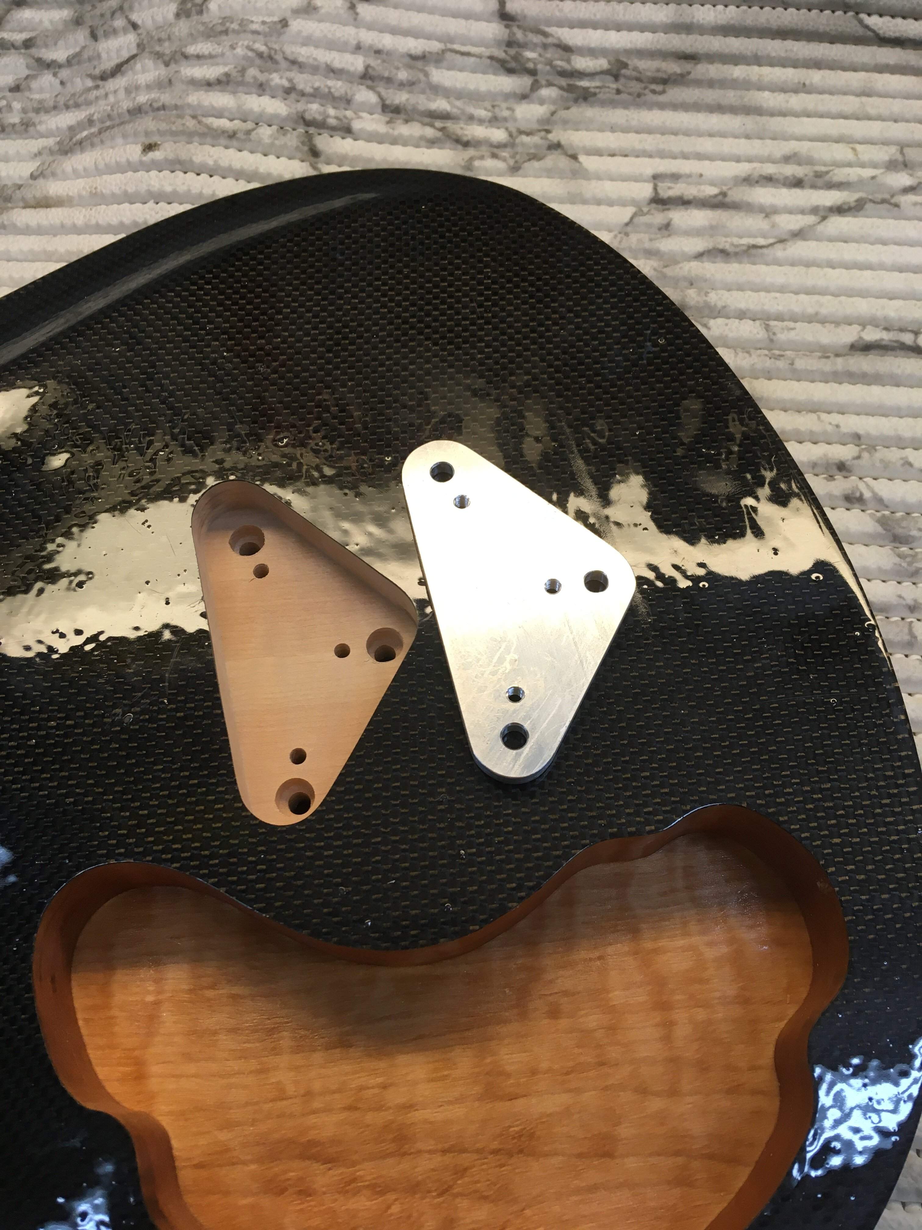
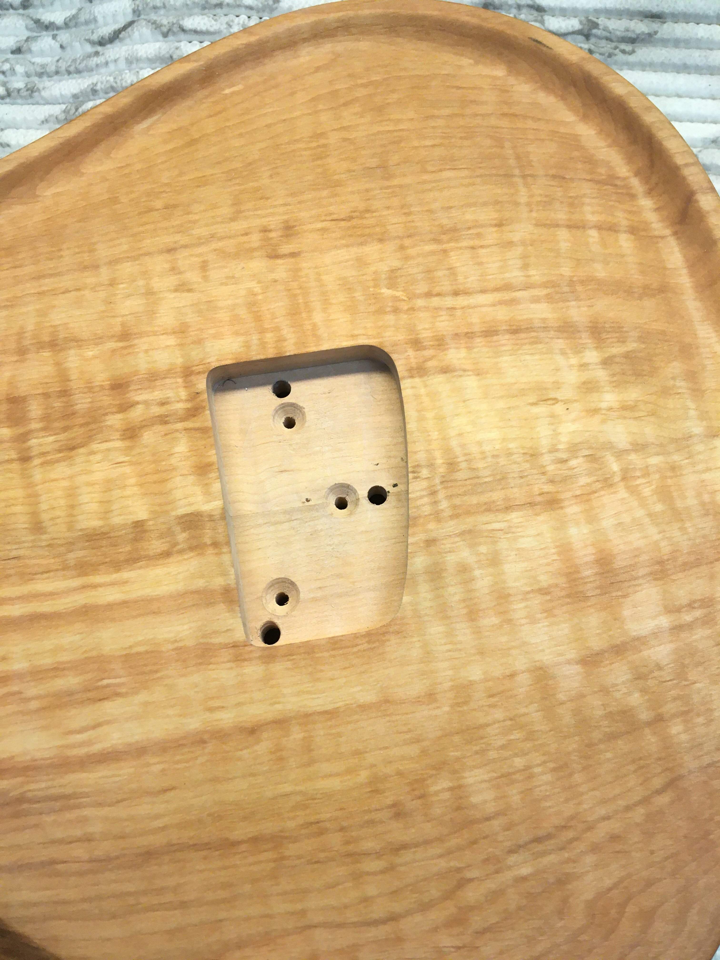
Tonight I made the bridge mounting and adjusting plate and routed a cavity for it. I don’t have all the machine screws, washers and locking nuts I need so I can’t show how it works yet. Original Parker bridge adjustment includes threaded inserts and clamp screws with both left and right hand threads on ends. I couldn’t find any with reasonable cost so I had to be a bit creative. I see Parker adjusment as a some kind of rear adjusted TOM variation. I try to get the needed hardware tomorrow and show you how my version works.
And this last coat of epoxy had zero fisheys!
And this last coat of epoxy had zero fisheys!
Here’s the bridge assembly. Aluminium plate is bolted in the rear cavity with machine screws. The long screws come thru the body in the threaded holes in the bridge. When turned clockwise the bridge goes down, turned counter clockwise the bridge goes up.
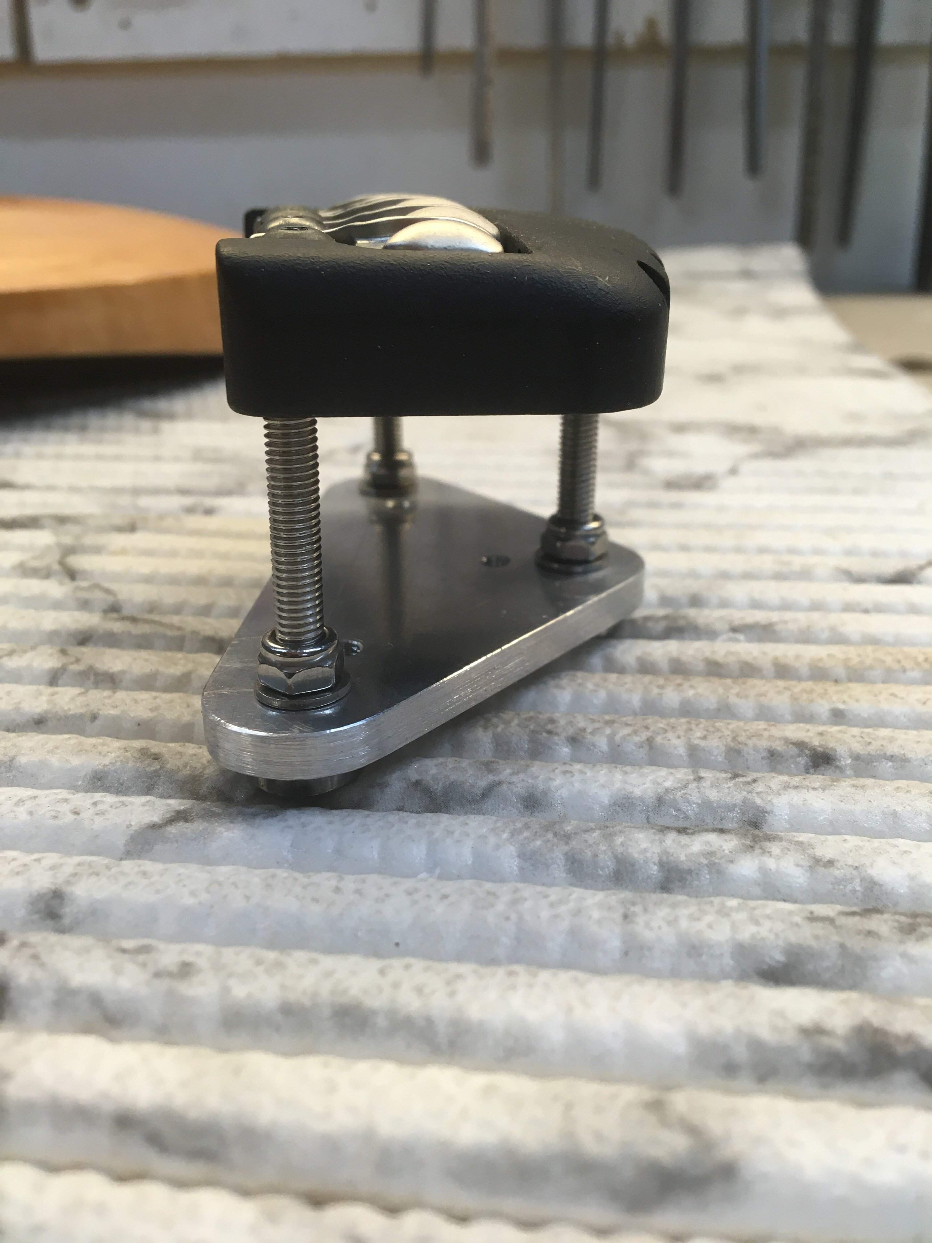
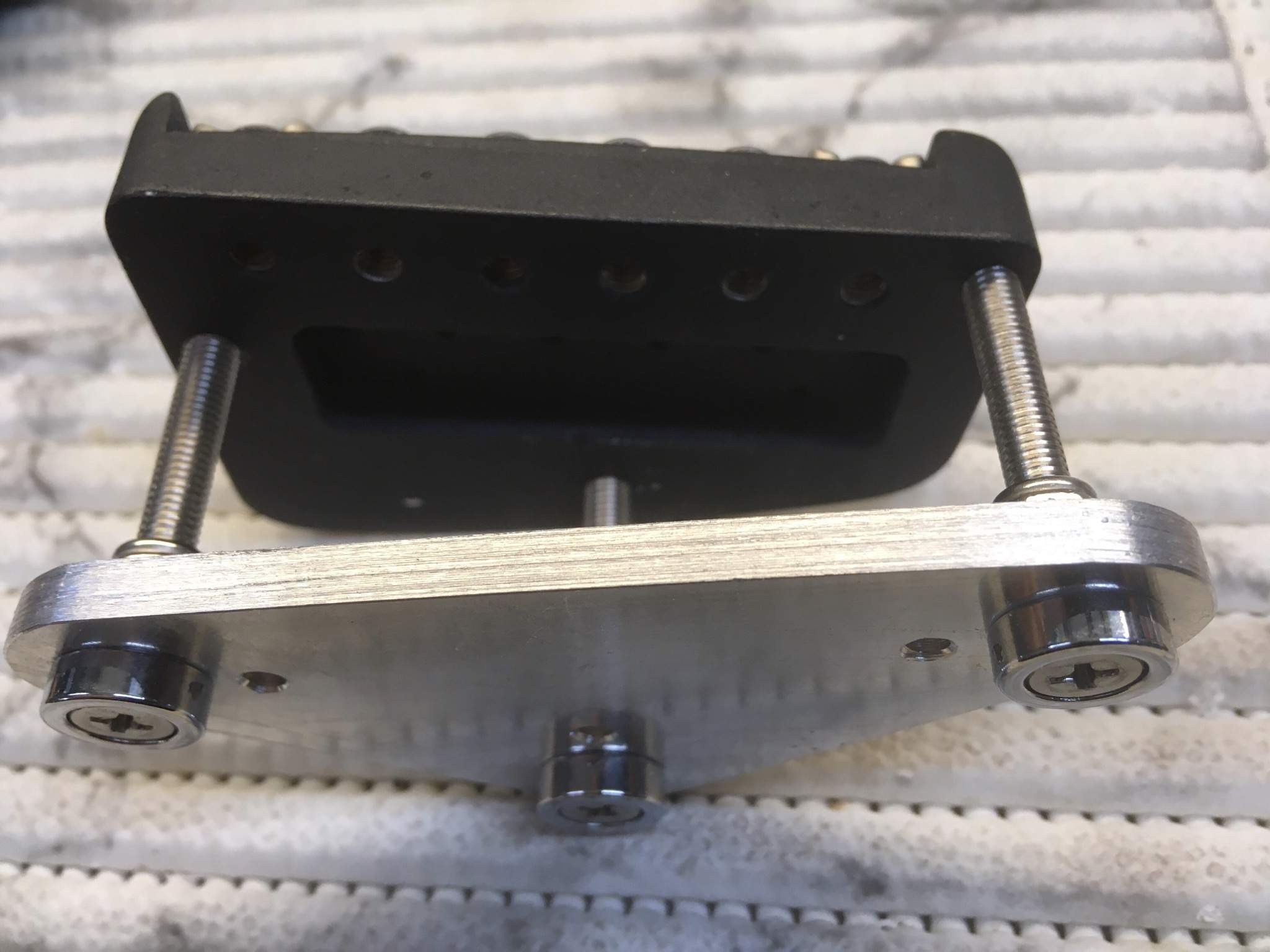
I sealed the back cavity with epoxy, that’s why there’s no pics of the bridge mounted. That pic will come tomorrow. I’m level sanding tomorrow as well.
I sealed the back cavity with epoxy, that’s why there’s no pics of the bridge mounted. That pic will come tomorrow. I’m level sanding tomorrow as well.

This bridge is new to me. It is interesting that the three machine screws are asymmetrically placed. I assume this means that, in addition to being able to raise and lower the bridge, you can tilt it in various ways.
Last edited:

Yes, the bridge tilts in all directions.This bridge is new to me. Interestingly, the three machine screws are asymmetrically placed. I assume this means that, in addition to being able to raise and lower the bridge, you can tilt it in various ways.


