

Enjoy the benefits of a premium membership!
Upgrade Account
-
TalkBass has been independent since 1998. Add your voice.
Create a free account to reply to discussions, view embedded media, and browse with fewer display ads.
Join free Log in
Want zero display ads or expanded classifieds tools? Compare plans.
You are using an out of date browser. It may not display this or other websites correctly.
You should upgrade or use an alternative browser.
You should upgrade or use an alternative browser.
Amp Guts Photos - Official Thread - Lets see those pics
- Thread starter svtb15
- Start date
More options
Who Replied?


Tell me more!!!
Chef posted the link already, but here's my take on it:
It's a modern sounding tube pre kit, no solid state parts with the exception of the power supply section. Active tonestack, huge sub bass from the bass boost switch. Super nice clean and crunch sounds. Switchable tuner out.
Downsides: no DI, no effects loop (though both can easily be added, there's lots of space).
Super hot output. I'm currently modding it to bring the output level down. My power amp is clipping with the master volume at 9:00.

Guts of a very early Demeter VTBP-201 preamp.
http://www.talkbass.com/forum/attachment.php?attachmentid=197267&d=1295995576
http://www.talkbass.com/forum/attachment.php?attachmentid=197267&d=1295995576

Mr. Foxen
Commercial User
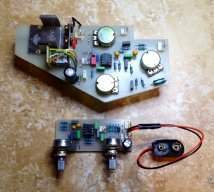

Thanks for the WTDI pics, duff2.
Are those TL072s I see? Can't read the part numbers. Looks like a fairly serious circuit with a double-sided board and all. Given the number of op amps, it could be very close to the WT's preamp circuit, minus the tube cathode-follower input, of course.
Are those TL072s I see? Can't read the part numbers. Looks like a fairly serious circuit with a double-sided board and all. Given the number of op amps, it could be very close to the WT's preamp circuit, minus the tube cathode-follower input, of course.

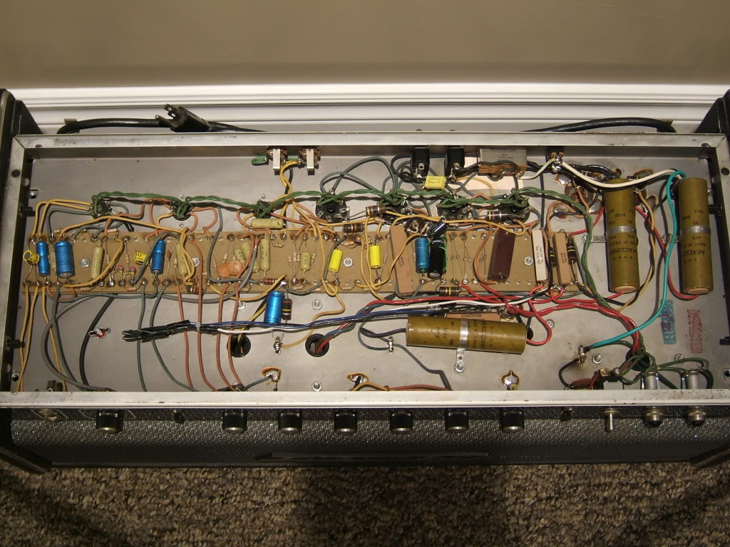
A top view of my 1973 Traynor YBA-3 Custom Special with the lid removed.
TD
TD
Actually, they're all 4558's. I guess that's why this pedal runs on 12-18 volts instead of 9.
I have read comments from some individuals that these op-amps have a rep for being noisy. That phenomenon must also depend on other circuit design factors because my WTDI is dead quiet.
Cheers,
Duff2
I have read comments from some individuals that these op-amps have a rep for being noisy. That phenomenon must also depend on other circuit design factors because my WTDI is dead quiet.
Cheers,
Duff2
Thanks for the WTDI pics, duff2.
Are those TL072s I see? Can't read the part numbers. Looks like a fairly serious circuit with a double-sided board and all. Given the number of op amps, it could be very close to the WT's preamp circuit, minus the tube cathode-follower input, of course.
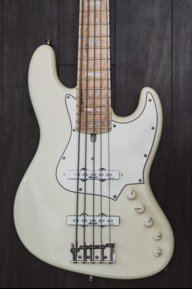
Now a turn for super compact heads..
Markbass F1
I'm still amazed how they manage to squeeze a conventional power amp with proper cooling in there.

father of fires
Commercial User
Chef posted the link already, but here's my take on it:
It's a modern sounding tube pre kit, no solid state parts with the exception of the power supply section. Active tonestack, huge sub bass from the bass boost switch. Super nice clean and crunch sounds. Switchable tuner out.
Downsides: no DI, no effects loop (though both can easily be added, there's lots of space).
Super hot output. I'm currently modding it to bring the output level down. My power amp is clipping with the master volume at 9:00.
Thanks for the review. It looks really cool. I've been looking for a new project. I may have to check this out.

father of fires
Commercial User
Chef posted the link already, but here's my take on it:
It's a modern sounding tube pre kit, no solid state parts with the exception of the power supply section. Active tonestack, huge sub bass from the bass boost switch. Super nice clean and crunch sounds. Switchable tuner out.
Downsides: no DI, no effects loop (though both can easily be added, there's lots of space).
Super hot output. I'm currently modding it to bring the output level down. My power amp is clipping with the master volume at 9:00.
Would adding a pot to bleed some of the signal to ground lower the output? Or is it not that simple?

Actually, they're all 4558's. I guess that's why this pedal runs on 12-18 volts instead of 9.
I have read comments from some individuals that these op-amps have a rep for being noisy. That phenomenon must also depend on other circuit design factors because my WTDI is dead quiet.
Cheers,
Duff2
They are old/obsolete devices and there are far better op-amps available today. Depending on how they were used they could be very noisy.
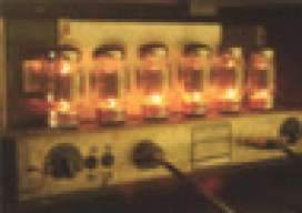
I have a few:
'73 Hiwatt 400w DR405
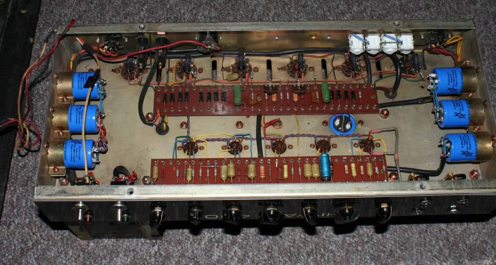
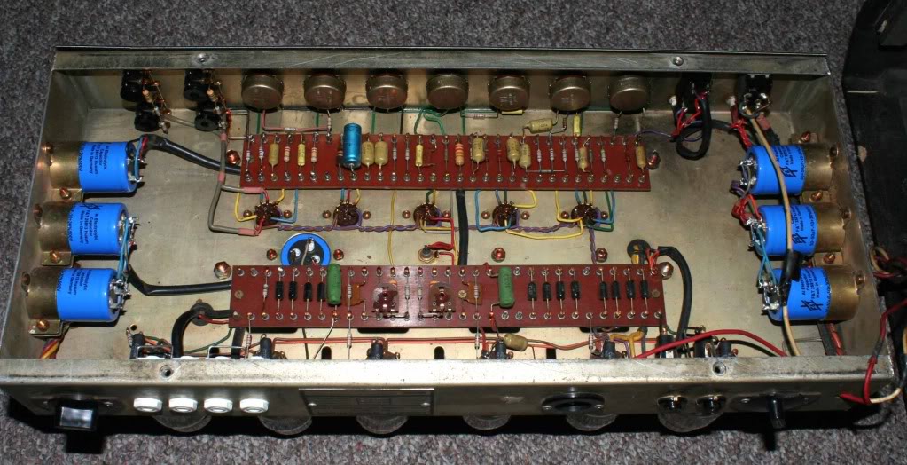
'74 Hiwatt 100w DR103
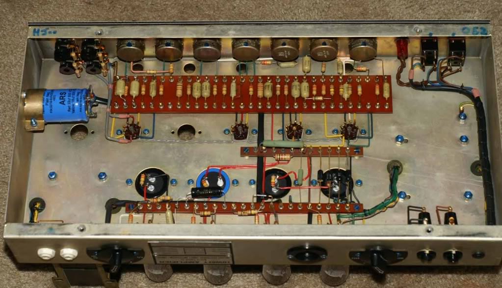
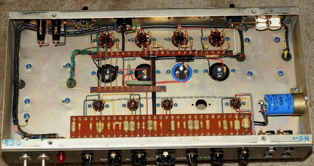
'78 Hiwatt 100 DR103
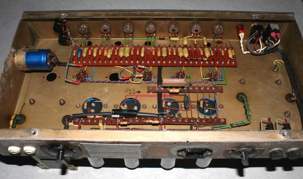
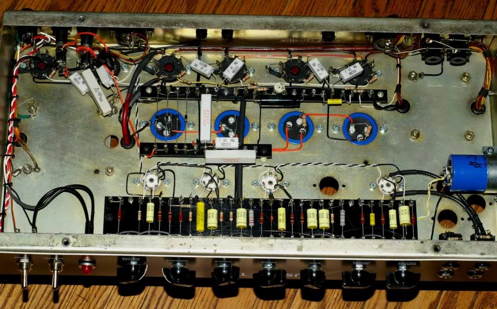
Sound City B120 re-wired with Hiwatt circuit
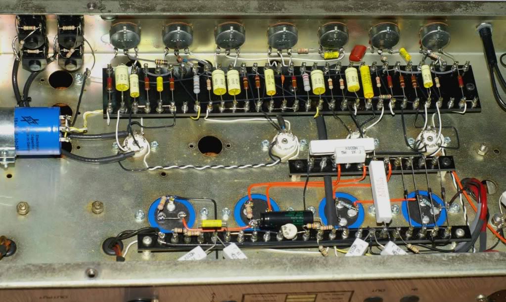
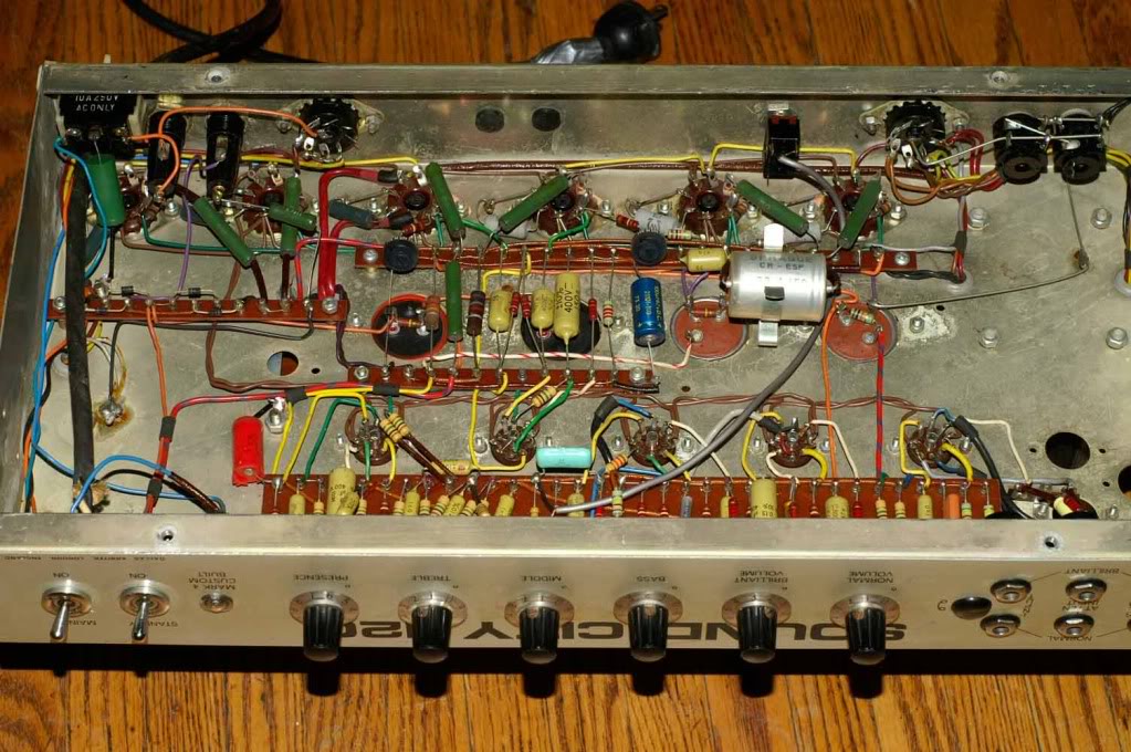
Sound City L120 mostly original. I had planned to convert this one but it sounds too awesome as is
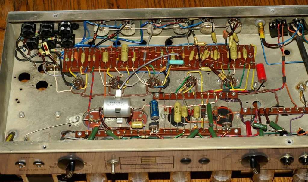
'73 Hiwatt 400w DR405
'74 Hiwatt 100w DR103
'78 Hiwatt 100 DR103
Sound City B120 re-wired with Hiwatt circuit
Sound City L120 mostly original. I had planned to convert this one but it sounds too awesome as is

I'm still amazed how they manage to squeeze a conventional power amp with proper cooling in there.
If you mean Class A/B, it is not; the F1 is Class D.
Would adding a pot to bleed some of the signal to ground lower the output? Or is it not that simple?
There's an even simpler solution: replacing a 100k resistor at the end with two smaller resistors in series, and connecting the output to them. That's the reason why it is on my bench, actually - I just haven't gotten around to it.
The kit is 230V - if you want to build it, you'll have to contact Martin at Madamp if he can provide a version with a 110V transformer.
father of fires
Commercial User
There's an even simpler solution: replacing a 100k resistor at the end with two smaller resistors in series, and connecting the output to them. That's the reason why it is on my bench, actually - I just haven't gotten around to it.
The kit is 230V - if you want to build it, you'll have to contact Martin at Madamp if he can provide a version with a 110V transformer.
Thanks for the tip and the heads up. This could be a cool summer project.


