Waiting for the knobs to arrive in the mail...

Enjoy the benefits of a premium membership!
Upgrade Account
-
TalkBass has been independent since 1998. Add your voice.
Create a free account to reply to discussions, view embedded media, and browse with fewer display ads.
Join free Log in
Want zero display ads or expanded classifieds tools? Compare plans.
You are using an out of date browser. It may not display this or other websites correctly.
You should upgrade or use an alternative browser.
You should upgrade or use an alternative browser.
Any DIY pedal builders on TB? Strut your stuff!
- Thread starter SubHuman
- Start date
More options
Who Replied?

My DIY activities for January. I didn't have any pcb's lined up for this month so I spent my time catching up on stripboard builds and troubleshooting headaches. Had two bitcrusher builds that weren't functioning properly and left me stumped. Put together this probe and testing rig to help troubleshooting. This is my coffee table workbench:
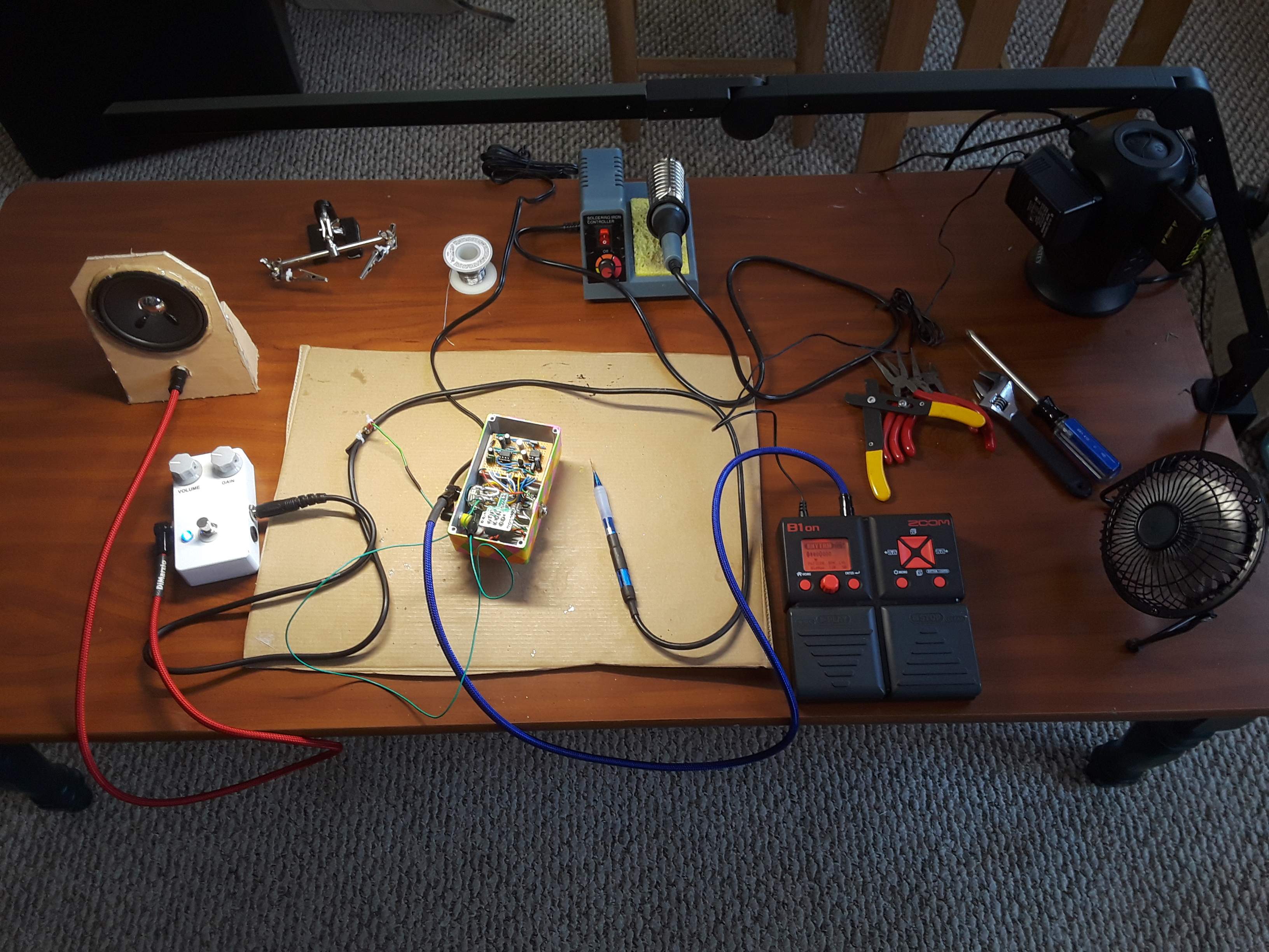
Built an audio probe from scrap. Probe uses the shell of a pen, with a 1uF MLCC cap inside between solid copper wires. Cord was a freebie 6ft instrument cable cut in half. Carefully carved away the sheath in the middle and soldered copper wire onto the braided shielding then attached a ground wire with alligator clip.
Speaker is made entirely from salvage materials and lots of hot glue. The speaker is a 3.5 inch 3Watt 8Ohm cone from a broken CD player boombox from 2003 (more on that later). The case shape was cut from cheap furniture drawer bottom board and glued together. 1/4" jack came from an old amp.
The white pedal is RunOffGroove Ruby amp built on stripboard to Bassman specs. Zoom B1on drum machine is used as a test signal.
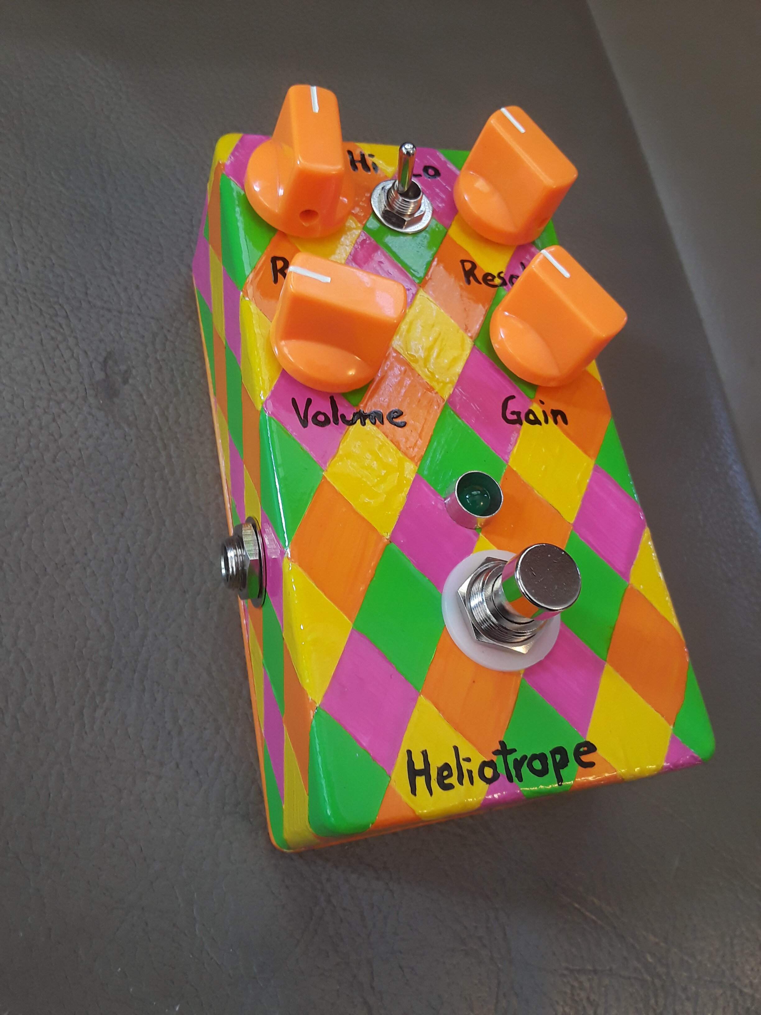
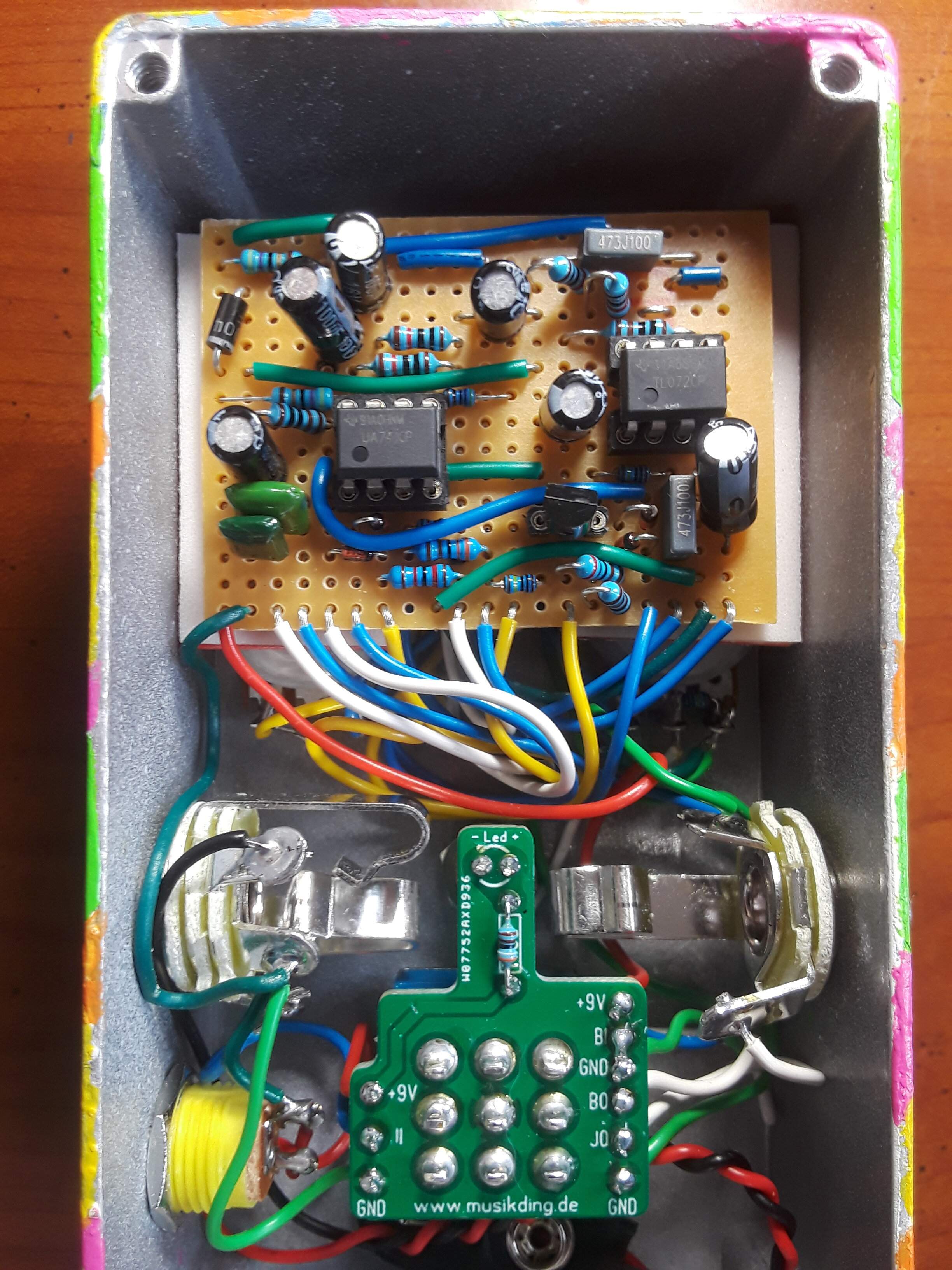
I used this setup to troubleshoot a Catalinbread Heliotrope built on stripboard. Probing revealed two channels on the IC's weren't functioning which pointed me toward a missing trace cut were they bled together.
This pedal used salvaged electrolytic capacitors from the same CD player mentioned earlier. Most of the caps measured in 10% below their rated values. Only one cap was rejected, a 22uF that measured in at 14uF.
Four-color checkered pattern is my most elaborate and time consuming use of masking tape to date.
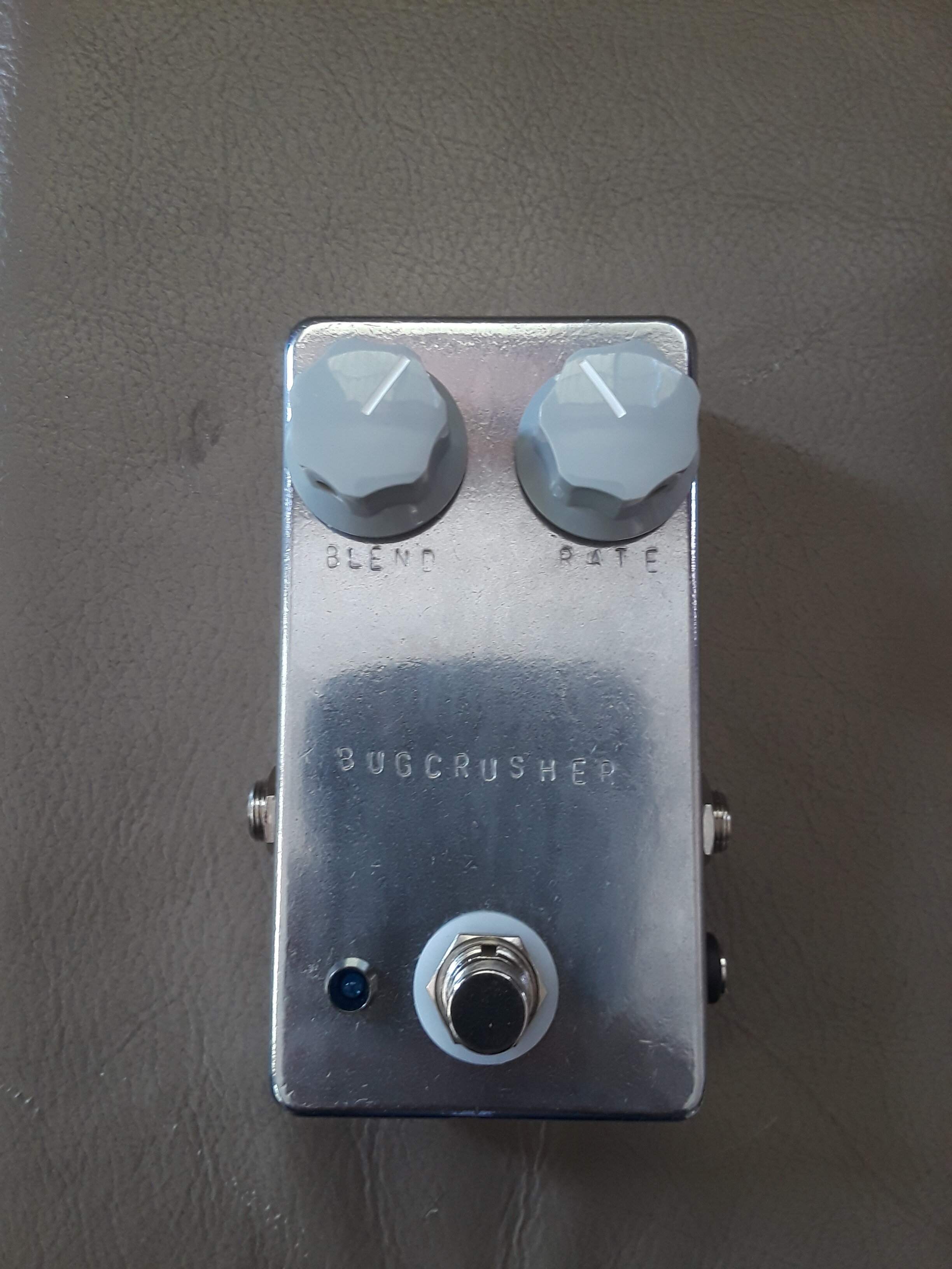
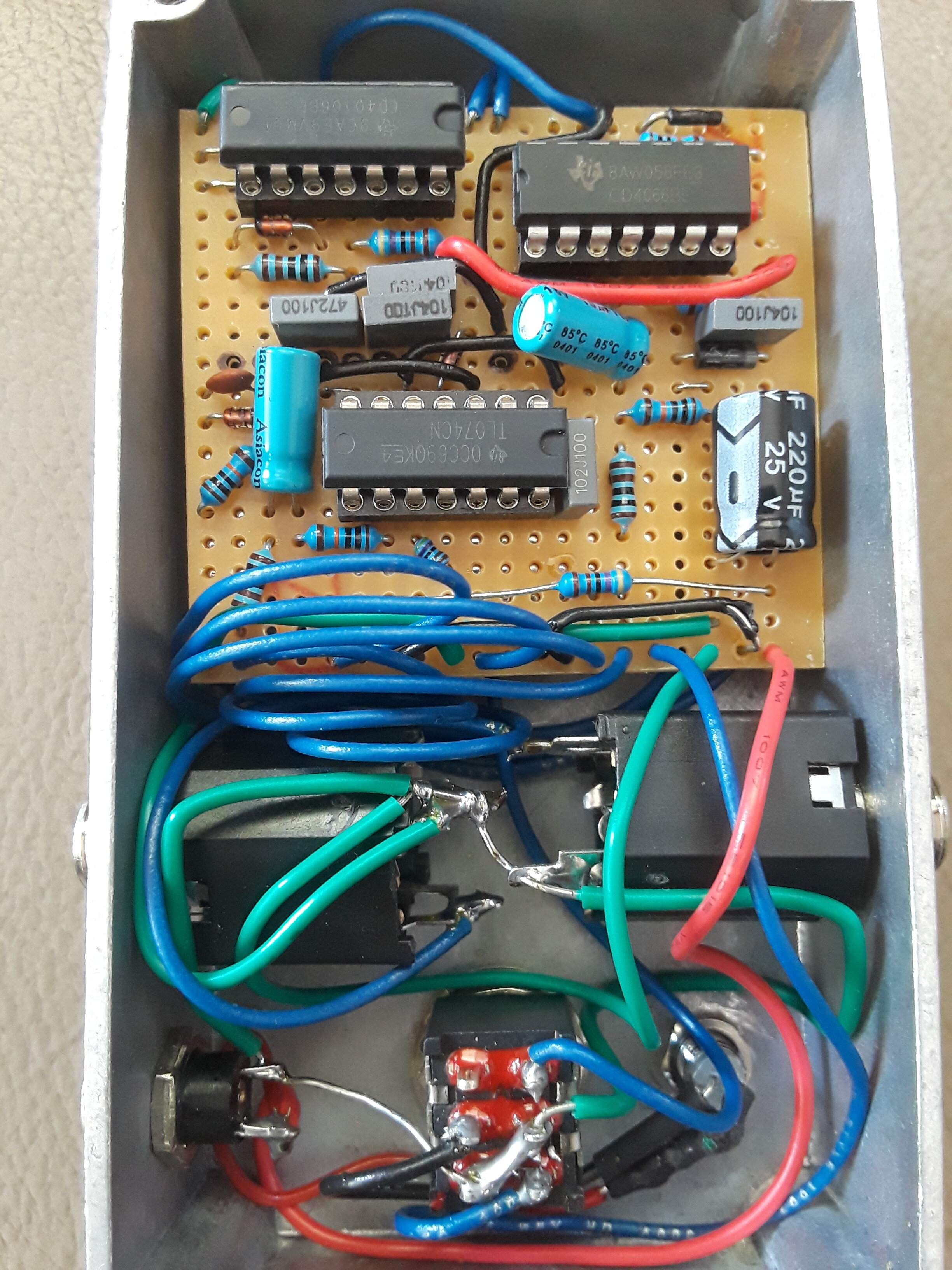
Second bit crusher is a BugBrand Bug Crusher that was built several months ago. Audio probe pointed me to the channel on the CD4066 that wasn't functioning where a group of jumpers were in the wrong position.
Built an audio probe from scrap. Probe uses the shell of a pen, with a 1uF MLCC cap inside between solid copper wires. Cord was a freebie 6ft instrument cable cut in half. Carefully carved away the sheath in the middle and soldered copper wire onto the braided shielding then attached a ground wire with alligator clip.
Speaker is made entirely from salvage materials and lots of hot glue. The speaker is a 3.5 inch 3Watt 8Ohm cone from a broken CD player boombox from 2003 (more on that later). The case shape was cut from cheap furniture drawer bottom board and glued together. 1/4" jack came from an old amp.
The white pedal is RunOffGroove Ruby amp built on stripboard to Bassman specs. Zoom B1on drum machine is used as a test signal.
I used this setup to troubleshoot a Catalinbread Heliotrope built on stripboard. Probing revealed two channels on the IC's weren't functioning which pointed me toward a missing trace cut were they bled together.
This pedal used salvaged electrolytic capacitors from the same CD player mentioned earlier. Most of the caps measured in 10% below their rated values. Only one cap was rejected, a 22uF that measured in at 14uF.
Four-color checkered pattern is my most elaborate and time consuming use of masking tape to date.
Second bit crusher is a BugBrand Bug Crusher that was built several months ago. Audio probe pointed me to the channel on the CD4066 that wasn't functioning where a group of jumpers were in the wrong position.

I've been meaning to build an audio probe myself. I have a makeshift one but yours has inspired me to make a proper one. That will be tonight's project. ThanksMy DIY activities for January. I didn't have any pcb's lined up for this month so I spent my time catching up on stripboard builds and troubleshooting headaches. Had two bitcrusher builds that weren't functioning properly and left me stumped. Put together this probe and testing rig to help troubleshooting. This is my coffee table workbench:
View attachment 4564936
Built an audio probe from scrap. Probe uses the shell of a pen, with a 1uF MLCC cap inside between solid copper wires. Cord was a freebie 6ft instrument cable cut in half. Carefully carved away the sheath in the middle and soldered copper wire onto the braided shielding then attached a ground wire with alligator clip.
Speaker is made entirely from salvage materials and lots of hot glue. The speaker is a 3.5 inch 3Watt 8Ohm cone from a broken CD player boombox from 2003 (more on that later). The case shape was cut from cheap furniture drawer bottom board and glued together. 1/4" jack came from an old amp.
The white pedal is RunOffGroove Ruby amp built on stripboard to Bassman specs. Zoom B1on drum machine is used as a test signal.
I used this setup to troubleshoot a Catalinbread Heliotrope built on stripboard. Probing revealed two channels on the IC's weren't functioning which pointed me toward a missing trace cut were they bled together.
This pedal used salvaged electrolytic capacitors from the same CD player mentioned earlier. Most of the caps measured in 10% below their rated values. Only one cap was rejected, a 22uF that measured in at 14uF.
Four-color checkered pattern is my most elaborate and time consuming use of masking tape to date.
View attachment 4564955
View attachment 4564957
Second bit crusher is a BugBrand Bug Crusher that was built several months ago. Audio probe pointed me to the channel on the CD4066 that wasn't functioning where a group of jumpers were in the wrong position.
View attachment 4564975
View attachment 4564977
Building a probe had been on my to-do list for half a year after my Bugcrusher fail. Failing a second time on another bitcrusher build with the Heliotrope was the motivation I needed. In the end, I could have fixed both if my eyes were sharp enough to spot my mistake. Was a big reassurance that no made mistakes were made on the stripboard layouts and simple absent minded mistakes during assembly is the cause of problems. Now I have a tool that provides some calm and sanity check when things go wrong.
Finally finished! My Markbass compressore went from this
To this!
Very cool! Paint one of my pedals too!?View attachment 4567616
View attachment 4567617
View attachment 4567619
View attachment 4567624
Finally finished! My Markbass compressore went from this
View attachment 4567627
To this!
View attachment 4567628

Built an audio probe from scrap. Probe uses the shell of a pen, with a 1uF MLCC cap inside between solid copper wires. Cord was a freebie 6ft instrument cable cut in half. Carefully carved away the sheath in the middle and soldered copper wire onto the braided shielding then attached a ground wire with alligator clip.
Speaker is made entirely from salvage materials and lots of hot glue. The speaker is a 3.5 inch 3Watt 8Ohm cone from a broken CD player boombox from 2003 (more on that later). The case shape was cut from cheap furniture drawer bottom board and glued together. 1/4" jack came from an old amp.
The white pedal is RunOffGroove Ruby amp built on stripboard to Bassman specs. Zoom B1on drum machine is used as a test signal.
great stuff!
would love to see a video of the probe in action
I'm not setup for making videos. Here's a close up photo of the probe with labeled parts.great stuff!
would love to see a video of the probe in action
Attachments

I'm not setup for making videos. Here's a close up photo of the probe with labeled parts.
View attachment 4570442
Yes! What a great little project!

Man, this has sat on my breadboard since March when I started my bathroom renovation. I got off my lazy behind and finished it today.
Peshauwm is a word my son came up with when he was in K to describe an alien ray from a ufo.
This is the first of 5 pedals I have parts for that are either rare or expensive, or both. One down!
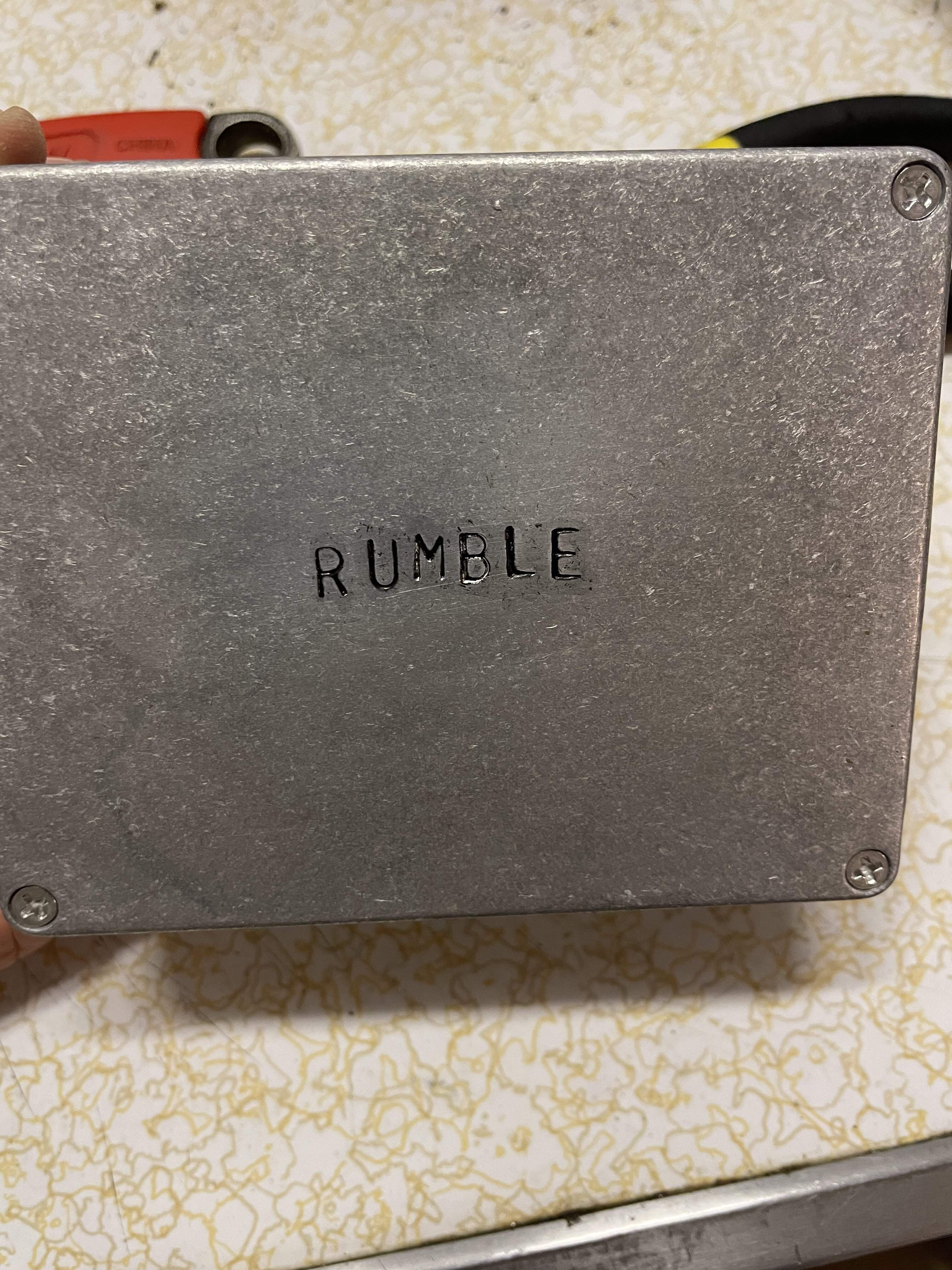
Spaceman Effects Rumble Fuzz, stripboard
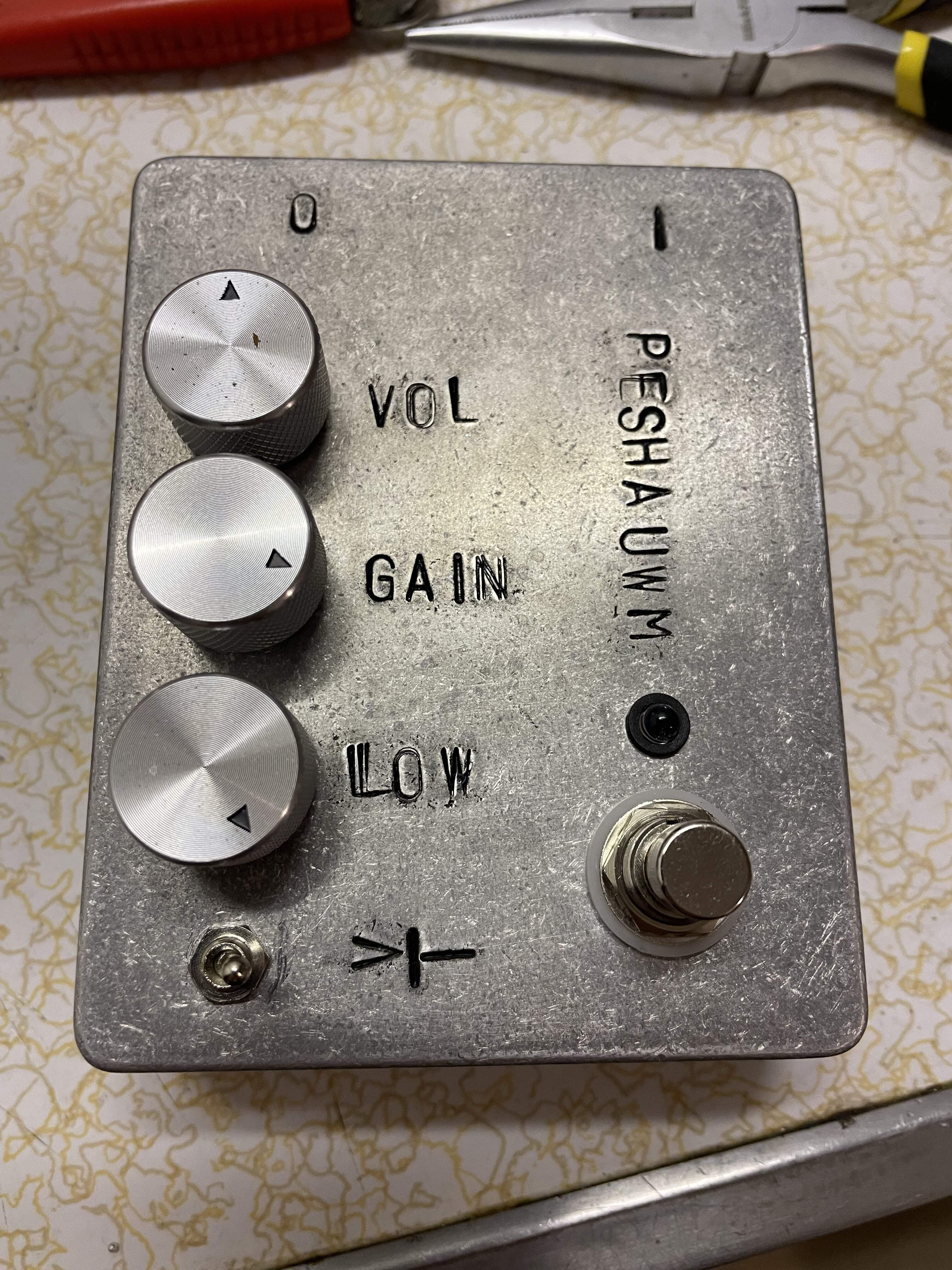
Peshauwm is a word my son came up with when he was in K to describe an alien ray from a ufo.
This is the first of 5 pedals I have parts for that are either rare or expensive, or both. One down!
Spaceman Effects Rumble Fuzz, stripboard
This is a passive pickup simulator for a guitarist friend. I’ll build one for myself but not something I’ll use a lot.
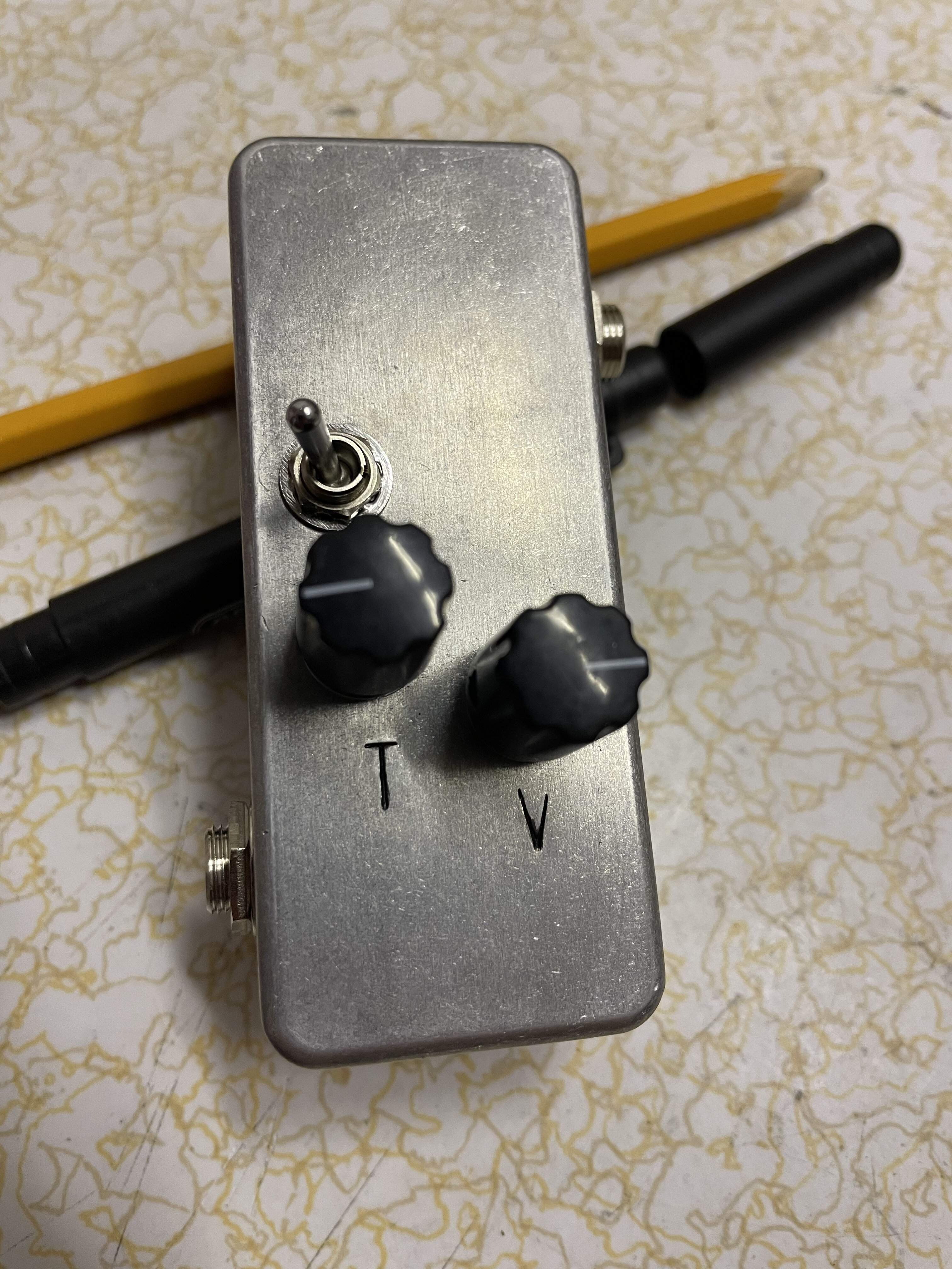

Lectric FX Flintlock Flanger
Has versatile controls and a sweet sound. Was difficult to calibrate without the necessary tools.
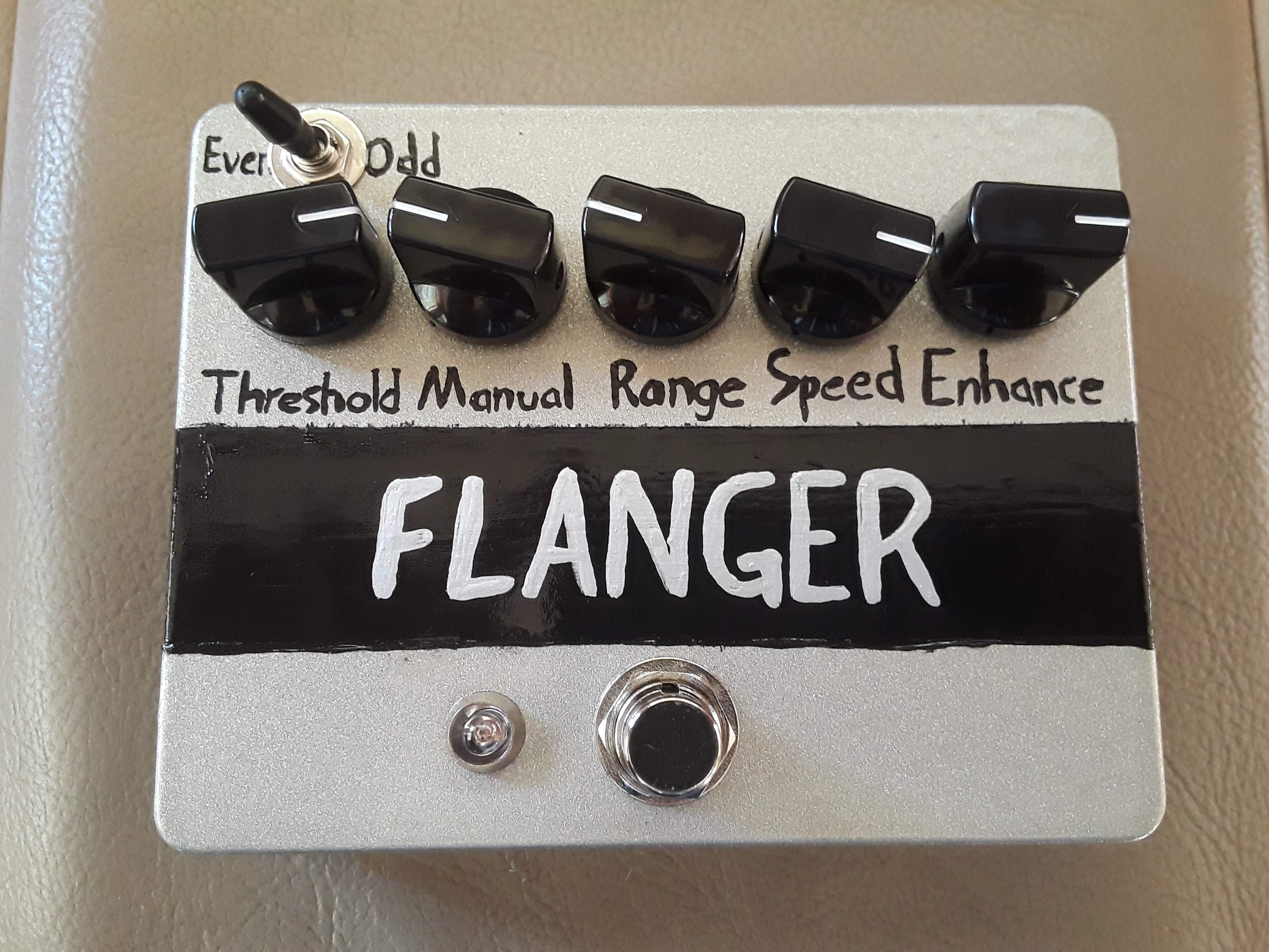
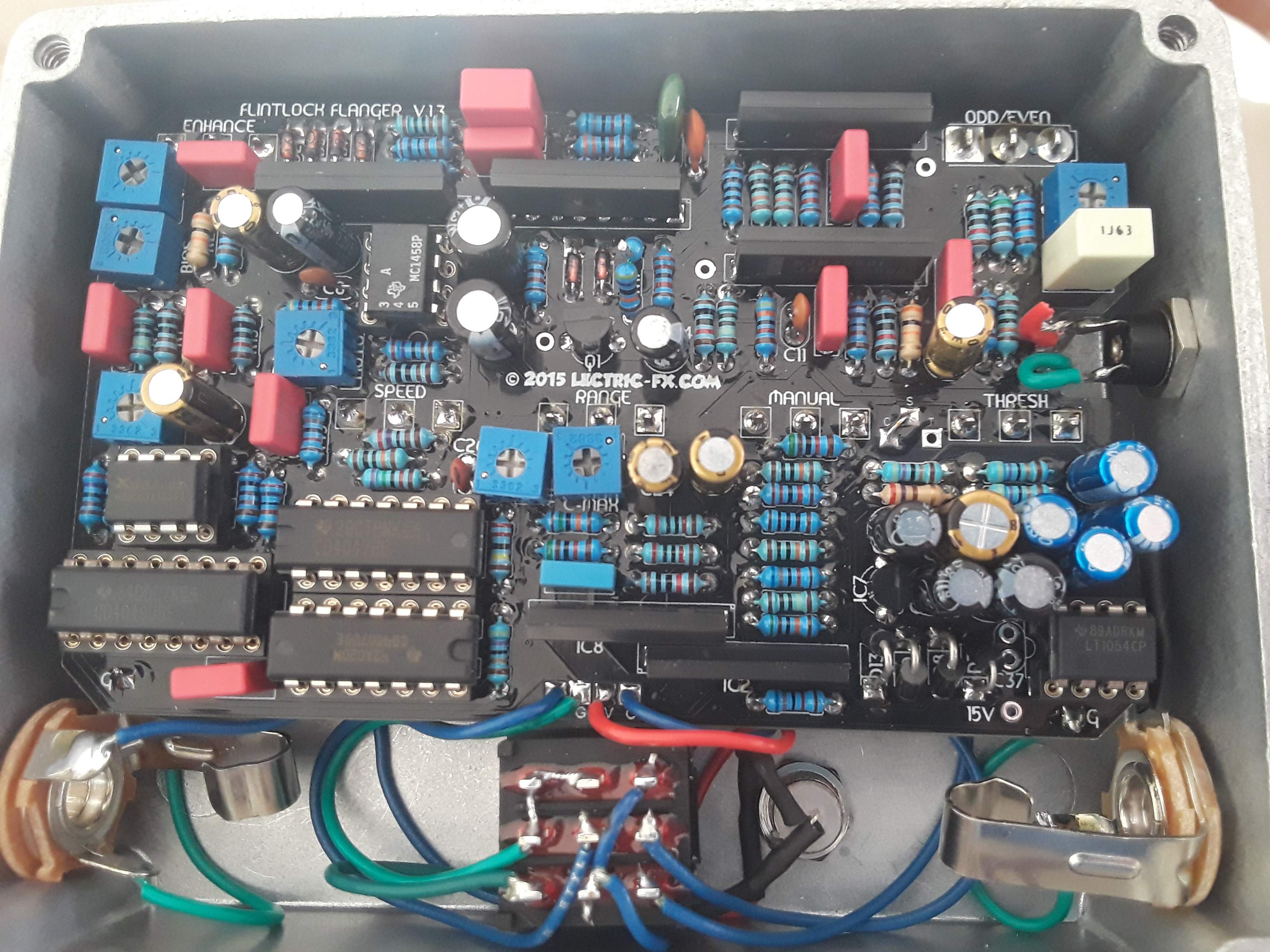
Has versatile controls and a sweet sound. Was difficult to calibrate without the necessary tools.

Quick question for the thread. Not sure if this is the right place to ask, but hey.
I misread some directions whilst soldering some LEDs and put them in reversed. Looking at the circuit diagram of these two pairs of opposing LEDs, am I right in thinking that it doesn't matter which one's which, just so long as they're opposite to each other?

Thanks for the help!
I misread some directions whilst soldering some LEDs and put them in reversed. Looking at the circuit diagram of these two pairs of opposing LEDs, am I right in thinking that it doesn't matter which one's which, just so long as they're opposite to each other?
Thanks for the help!
They should work just fine. As long as they are opposite each other.Quick question for the thread. Not sure if this is the right place to ask, but hey.
I misread some directions whilst soldering some LEDs and put them in reversed. Looking at the circuit diagram of these two pairs of opposing LEDs, am I right in thinking that it doesn't matter which one's which, just so long as they're opposite to each other?
View attachment 4583402
Thanks for the help!
They should work just fine. As long as they are opposite each other.
Thanks

here's a recent one for my personal collection--MXR Blue Box clone with a boost on the output and a toggle for -1 octave or -2 octaves
here's a recent one for my personal collection--MXR Blue Box clone with a boost on the output and a toggle for -1 octave or -2 octaves
Nice!
I used to watch Yellow Submarine all the time as a kid. So, extra points!

- Feb 16, 2008
- 21,240
- 23,638
- Disclosures
- John K Custom Basses
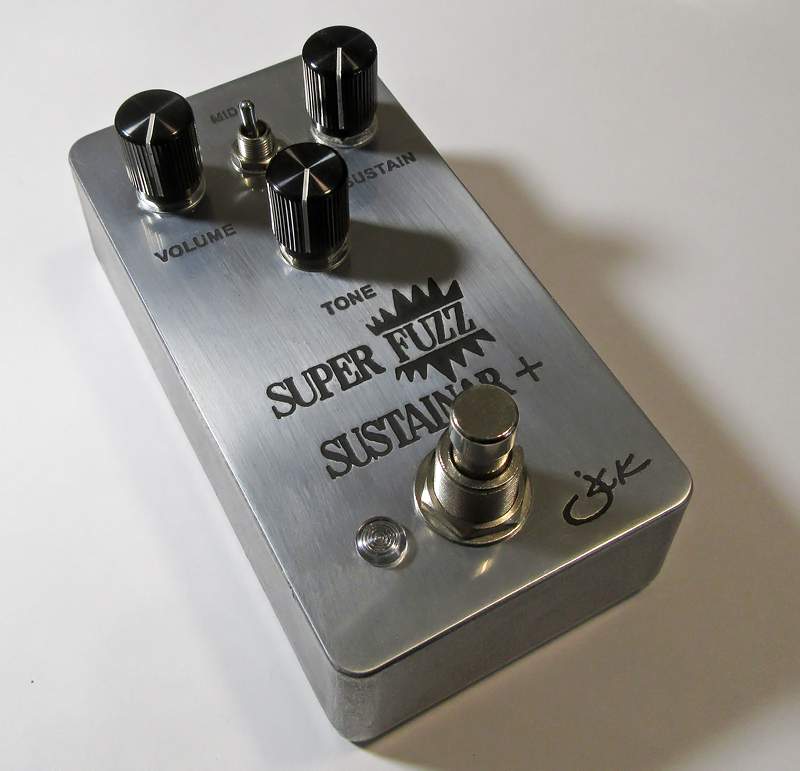
Elk Super Fuzz Sustainar + ( aka EQD Hizumitas) clone. The "+" stands for an added mids boost switch. it also has a relayed true bypass.