• TalkBass has been independent since 1998. Add your voice.
    Create a free account to reply to discussions, view embedded media, and browse with fewer display ads.
    Join freeLog in
    Want zero display ads or expanded classifieds tools? Compare plans.

Devil Magnum

I would drill those holes from both sides. Drill a small hole down from the top, aiming for the ferrule hole, but only halfway in. Then drill a larger size hole up from the ferrule hole, to meet in the middle. That way you can make sure both ends of the hole are in the right places. A small misalignment where they meet will be hidden.
 
I would drill those holes from both sides. Drill a small hole down from the top, aiming for the ferrule hole, but only halfway in. Then drill a larger size hole up from the ferrule hole, to meet in the middle. That way you can make sure both ends of the hole are in the right places. A small misalignment where they meet will be hidden.

Yes, I'm finding this is the correct tact. I need to buy a drill-bit for the bridge-post holes first.
 
Working on this phase of the project reminded me why people make "cookie-cutter" basses that look like Fender's. And nothing against Fender basses - I love them and own a few. But that path has been transversed countless times, is safe and predictable and since it is so basic and thoroughly documented - pretty much anyone with basic shop skills can successfully produce their own version. And mass produced makers can have them made like McDonalds hamburgers and make money selling them for MIC prices.

Not so this bass... which is a unique, one-off design that has all sorts of details that take it way out of the "cookie-cutter" frame. Including this wafer-thin neck wedge/spacer to achieve the ideal string angle for an ideal set-up.
upload_2021-3-22_21-37-41.jpeg

The more the neck heal interfaces with the pocket - the greater/more dynamic the sonic connection of neck and body. (these are not readily available...)
upload_2021-3-22_21-42-14.jpeg

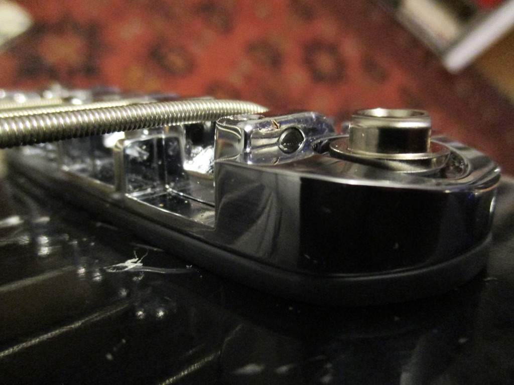
Once I drilled holes for the bridge post anchors - I determined that to achieve the proper height of the bridge I needed to create a riser/spacer of lucite. Hard to see but it's 1/8". I forgot to take a pic of it before assembling to adjust string height/intonation etc so will add a pic of it later when I take it apart. Another custom fabrication made exclusively for this bridge/bass.
upload_2021-3-22_21-45-0.jpeg

Also idiosyncratically designed/created is the string-thru to string-stop ferrules at the angled butt of the bass. (sorry, I don't know how else to refer to it as...) My calculations positioning the bridge for proper intonation were successful - I lose sleep over such and am always relieved when it all works out. Mimicking a generic Fender bass is soooo easy by comparison. I luckily had an old set of strings to use as my "set-up/test" set. I used the recommended two approaches (from either side) to create the ideal string channel from ferrule to body exit at the bridge. Much fussing to align and coordinate the exit ports from the body, through the pg and spacer to the saddles. All in a days work... FTR - clear plastic still on the pg. I will order from this eBay seller again as the pg had two layers of clear on the shiny-side. When you are doing a lot of work fitting/measuring etc - the extra clear plastic layer is really appreciated to keep the shiny side intact/unscratched.
upload_2021-3-22_21-53-12.jpeg

Retro rockets ready for firing!
upload_2021-3-22_22-5-57.jpeg

Worked out exactly where the DS/BS pu will reside - over time I've found my own "sweet-spot" through trial & error and stick with it to assure a totally rockin' bass. Especially with these pu's. (spoiler: not P-bass pu location)
upload_2021-3-22_22-0-40.jpeg

...speaking of which - this showed up today.
upload_2021-3-22_22-7-58.jpeg

Superior tone indeed - any bass with one of these installed is a guaranteed tone-monster. 500k stacked V/T pot and .047uf cap will deliver the goods.
upload_2021-3-22_22-8-43.jpeg


upload_2021-3-22_22-23-39.jpeg

7lbs/1oz sans pu/electronics.
upload_2021-3-22_22-24-6.jpeg
 
Last edited:
I so hear you on how a bespoke instrument is so much more work, mentally and physically, but I do so love the challenge :thumbsup: This is really coming together nicely!

:) Thanks! This is what I love about our connection here - we are all going through similar idiosyncratic/individualistic challenges and I agree with you completely. Making a Fender clone is just not what we do :) - I'm happy to be a part of this thread filled with like-minded peeps like you Beej. Coloring "outside the box" is our default. :bassist:
 
On the other thread about drawing software, we were talking about the difference between CAD programs and Illustrating programs. Many of the folks were eager to "design" their basses in a computer, mostly so that they could work with the curved outer perimeter lines. Bezier curves to make a nice picture of what the bass looks like. And then print out a full size pattern of that cool shape. Okay, that's what programs like Illustrator are for.

What JIO is going through above is what a CAD program like AutoCad or Qcad is for. The engineering of the functional core of the bass. Making all the functional parts fit together and work correctly. The little numbers and dimensions. Work it all out first in CAD. Especially on a non-Fender (aka Crazy) bass design like this.
 
Is there a fairly consistent standard for the height of the finished fingerboard and bridge saddles above the body on electric basses,.....
Or does it vary quite a bit, depending on scale length (and other factors, but I can't think of any)?
 
  • Like
Reactions: JIO
Love this bass.
Is there a fairly consistent standard for the height of the finished fingerboard and bridge saddles above the body on electric basses,.....
Or does it vary quite a bit, depending on scale length (and other factors, but I can't think of any)?
It can vary quite a bit; Within the Fender world, the standard is around 3/8".
 
  • Like
Reactions: JIO
Beautiful work on those string anchors, JIO! I love that kind of functional aesthetic.

Is there a fairly consistent standard for the height of the finished fingerboard and bridge saddles above the body on electric basses,.....
Or does it vary quite a bit, depending on scale length (and other factors, but I can't think of any)?

For a zero-neck-angle bass (i.e., Fender) it’s pretty standard and easy.

For angled necks (i.e., Gibson) it can vary quite a bit, and it’s best to have hardware in hand to measure and calculate the geometry.

Then there are oddballs like Rickenbacker....
 
Is there a fairly consistent standard for the height of the finished fingerboard and bridge saddles above the body on electric basses,.....
Or does it vary quite a bit, depending on scale length (and other factors, but I can't think of any)?

As has already been noted, it can vary depending on the individual basses details. This one needed a slight angle in the pocket due in part to having the bridge sitting on the pg and needing to allow for the height of the DS/BS pu which is also sitting on the pg. That pu has adjustable poles (a feature of its design) but the pu itself (about 3/8" in height) is static once installed. The Hipshot bridge allows for a lot of height adjustment but I got it as 'flat' as possible to maintain its grounding stability. Saddles have slight gaps at their base - enough for lowering if needed. (i.e, not bottomed out) It's a cool new bridge design from Hipshot that fits this bass like a glove aesthetically. :thumbsup:
 
Last edited:
Love this bass.

It can vary quite a bit; Within the Fender world, the standard is around 3/8".

Beautiful work on those string anchors, JIO! I love that kind of functional aesthetic.

For a zero-neck-angle bass (i.e., Fender) it’s pretty standard and easy.

For angled necks (i.e., Gibson) it can vary quite a bit, and it’s best to have hardware in hand to measure and calculate the geometry.

Then there are oddballs like Rickenbacker....


:) Thanks guys! Once you get a new bass to a certain point - you know you're out of the woods and can start feeling confident that your imagined concepts hold water. Yesterdays work put me at that point. Today I'll rout for the pu and electronics/controls and once that's done the body will be final sanded and sent to Pat.

I'll install this UK-style jack just below the stacked knob angled toward the bridge. It's a clean, minimal design that I was turned-on to dealing with my Burns and Watkins basses. I considered other locations but functionally like a face-mount using a 90degree cord plug as it lays flat below the bridge looped under the strap.
upload_2021-3-23_8-17-25.jpeg
 
Many of the folks were eager to "design" their basses in a computer, mostly so that they could work with the curved outer perimeter lines. Bezier curves to make a nice picture of what the bass looks like. And then print out a full size pattern of that cool shape. Okay, that's what programs like Illustrator are for.
Was there ever a time when you didn't have a computer program to "design" the shape and style of a bass body and simply freehand drew it?
 
  • Like
Reactions: JIO
Was there ever a time when you didn't have a computer program to "design" the shape and style of a bass body and simply freehand drew it?

You mean like most of the classic guitar designs that are still popular today? ;) Out of all electric guitar/bass history, I'd love to see a pic of (George Fullerton?) at the drawing table drawing the first Fender P-bass or Strat.
 
Last edited:
I draw mine out on vellum, take the drawing to the FedEx Store for the large format copier, and work from there.

The fiddly dimensions I do with careful measurements and a calculator. Funny, I'm a software engineer by day, but prefer to do a lot of stuff the old-fashioned way with pencil and paper (most software frustrates me :roflmao:)
 
I do pen and paper too, but that's also coming from a background of many years of drawing, painting and design, so it's easy for me to bang off a full-sized drawing with a pencil and end up with balanced and flowing curves and lines. I know this is not an inherent skill for lots of people, so it's not for everyone and may end up creating frustration for some, but it's satisfying for me. :D I can use graphics and illustration programs no problem, but I've not done the learning curve of CAD...something I should really do... :thumbsup:

 
  • Like
Reactions: Supadope and JIO
I draw mine out on vellum, take the drawing to the FedEx Store for the large format copier, and work from there.

The fiddly dimensions I do with careful measurements and a calculator. Funny, I'm a software engineer by day, but prefer to do a lot of stuff the old-fashioned way with pencil and paper (most software frustrates me :roflmao:)

I use a few devices including the coin operated copy machine at my local library. :) As you saw in my early post I grid paper and draw (the body) contour by hand. Shaping from there is penciled on the cut-out body and rasped or routed. I have had a couple CAD bodies made from my original design which is cool but the original body that I made by hand was handed to someone else to scan and reproduce.

I would imagine that computer software can be frustrating for everyone at a certain point! :D
 
  • Like
Reactions: Beej
I do all the engineering work in CAD (Qcad, these days). That is, I do all the detail work, fitting all the hardware, making sure the strings are positioned correctly and have the right clearance and adjustment range, locating the pickups and controls, etc. The functional part of the design process.

While doing that, I draw out the perimeter shape and other curved shapes like internal chambers and control cavities, using the Polylines function in CAD. It establishes the curved shapes as a series of points with short straight line segments between them. It's quick and simple, and it makes sure that the curved shape fits correctly with the core stuff. I typically draw them with the points anywhere from 1/4" to an inch apart. Those Polylines get copied into other layers in the drawing, to become patterns and templates.

To make the patterns and templates, I print the Polylines out full size, with the important reference holes to locate them. I usually print them on heavy 28lb paper. I transfer the Polylines and reference hole locations to pieces of 3/4" MDF, sometimes using old-fashioned carbon paper under the paper printout. Other times I cut out the paper template and draw around it with a pencil. What is drawn on the MDF is the Polyline; points and segments.

I saw out the MDF and smooth it all out with spindle sanders and hand files. This is where I convert the Polyline into an actual curved line. I'm careful to meet all the points and make a smooth curved shape between them. The MDF pattern becomes the Master Pattern. It is the actual shape that all the instruments will be cut to. It's a full size physical thing that I can look at and feel with my hands, and verify that the shape is what I want.

In the computer, I leave the perimeter shape as a Polyline. It's not the actual curved line that's on the Master Pattern, but it's an accurate representation of all the critical points. Yeah, I could smooth the Polyline using a Polyline Smoothing function, or paste it into an Illustrator-type program and fit a Bezier curve to it. But that's only if I wanted to make the CAD drawing "pretty" to show to people. Generally not worth the extra time to me.

That's my design process: I use Qcad to establish all the important dimensions and locations. I use Polylines within Qcad to rough out all the curved shapes. Then I transfer the Polylines to hard MDF patterns, and do the final smoothing of the curved shapes with tools, on the MDF.
 
Here's a pic of the bridge spacer.
upload_2021-3-23_17-1-15.jpeg

Control and pu cavities routed, pu wire channel drilled and ready for a final sanding.
upload_2021-3-23_16-56-48.jpeg

Final mockup with all parts - 7lbs/6oz. Will wait until the body comes back finished to wire it up. All tolerances are set - will just need final assembly, stringing it up and plugging it in.
upload_2021-3-23_16-56-2.jpeg
upload_2021-3-23_16-56-19.jpeg

While the body is away waiting to be finished, I'll do fussy work on the pg so the edges are refined. Will also work on the two upper pg finger rests.
upload_2021-3-23_17-3-27.jpeg
