• TalkBass has been independent since 1998. Add your voice.
    Create a free account to reply to discussions, view embedded media, and browse with fewer display ads.
    Join freeLog in
    Want zero display ads or expanded classifieds tools? Compare plans.

Router Planing Fixtures

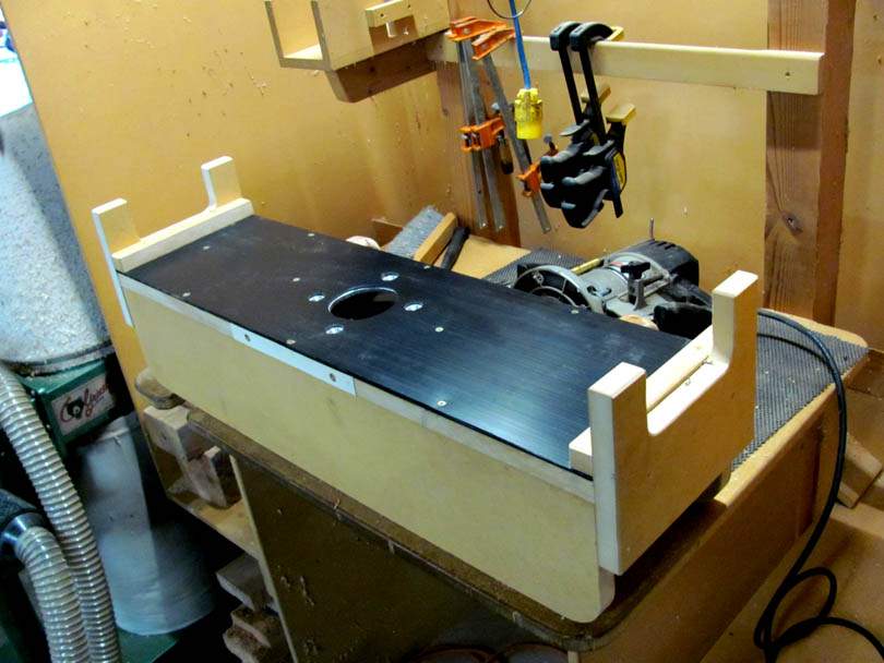
And here's the sheet of black 1/8" thick Super Slippery UHMW plastic, cut and fitted to the bottom side of the bridge assembly. Now it should slip and slide easily on the aluminum rails. The MDF bottom plate slid okay, but this bridge is heavy enough that I was afraid it was going to wear grooves in the MDF. The UHMW shouldn't wear at all.

IMG_7695B.jpg
 
Adding more detail features to the bridge of the Super Router Planing Fixture.

If you remember, the original Router Planing Fixture had a wood strip with a row of pins sticking down. They dropped on either side of the left side rail, and guided the bridge down the length of the bed in straight parallel paths. They worked really well, making the router planing operation faster and more uniform.

For the new improved Super Router Planer Fixture, I went with an aluminum bar with milled notches. It's a piece of 1/8" x 1" aluminum bar stock, with 1/2" wide notches milled spaced 1 3/4" apart. Same idea as before; the notches hook loosely over the left side aluminum rail.

Milling the aluminum notch bar. Yeah, I could have cut the notches with a bandsaw or hacksaw and a square file. But life is easier with a milling machine.

IMG_7696B.jpg


Here's the notch bar mounted on the front left side of the bridge.

IMG_7697B.jpg


In operation. I spaced the notch bar up slightly so the tops of the notches don't drag on the aluminum. I aligned it so that the center notch takes the router right down the center of the bed. Then there are four notches on either side. Surfacing my Scroll Bass walnut blanks, it'll only take 7 passes to cover the width. The old fixture was 13 passes. That's the advantage of the big 2" router bit.

Even fully loaded, the bridge slides very easily down the rails. The UHMW sheet sliding on the aluminum rails works very well.

IMG_7698B.jpg


I also added a sliding depth stop. The PC router had a 3/8" steel rod that contacts the little stop turret down on the base. Too hard to see it down inside the bridge. So, I swapped out the rod for a longer 3/8" stainless rod, and added this MDF bracket that it sticks up through. Now I just have to make up a quick collar with a thumbscrew that can be positioned on the stainless rod.

IMG_7699B.jpg


This monster is almost ready to start some test runs ploughing wood! I've got a stack of walnut and mahogany body blanks waiting for it. Yesterday Keith dropped off two 2" guitar body blanks that need to be thinned down. They will also be good test pieces.
 
Adding more detail features to the bridge of the Super Router Planing Fixture.

If you remember, the original Router Planing Fixture had a wood strip with a row of pins sticking down. They dropped on either side of the left side rail, and guided the bridge down the length of the bed in straight parallel paths. They worked really well, making the router planing operation faster and more uniform.

For the new improved Super Router Planer Fixture, I went with an aluminum bar with milled notches. It's a piece of 1/8" x 1" aluminum bar stock, with 1/2" wide notches milled spaced 1 3/4" apart. Same idea as before; the notches hook loosely over the left side aluminum rail.

Milling the aluminum notch bar. Yeah, I could have cut the notches with a bandsaw or hacksaw and a square file. But life is easier with a milling machine.

View attachment 4301053

Here's the notch bar mounted on the front left side of the bridge.

View attachment 4301054

In operation. I spaced the notch bar up slightly so the tops of the notches don't drag on the aluminum. I aligned it so that the center notch takes the router right down the center of the bed. Then there are four notches on either side. Surfacing my Scroll Bass walnut blanks, it'll only take 7 passes to cover the width. The old fixture was 13 passes. That's the advantage of the big 2" router bit.

Even fully loaded, the bridge slides very easily down the rails. The UHMW sheet sliding on the aluminum rails works very well.

View attachment 4301055

I also added a sliding depth stop. The PC router had a 3/8" steel rod that contacts the little stop turret down on the base. Too hard to see it down inside the bridge. So, I swapped out the rod for a longer 3/8" stainless rod, and added this MDF bracket that it sticks up through. Now I just have to make up a quick collar with a thumbscrew that can be positioned on the stainless rod.

View attachment 4301056

This monster is almost ready to start some test runs ploughing wood! I've got a stack of walnut and mahogany body blanks waiting for it. Yesterday Keith dropped off two 2" guitar body blanks that need to be thinned down. They will also be good test pieces.

I'd contemplated putting headless nails at intervals on mine to give it the same kind of variable slot behavior, but I didn't/don't have the same slippery plastic you do or aluminum rails so it wasn't going anywhere without a little effort, lol. I did wonder if by not having something like that if it would be a problem if the bridge pivoted while in use... Not enough to go off the rails, but just that there was no guarantee I would be keep a straight line and if the bridge sides didn't stay even (i.e. square to the run of the rails) if there would be ill effects.
 
I'd contemplated putting headless nails at intervals on mine to give it the same kind of variable slot behavior, but I didn't/don't have the same slippery plastic you do or aluminum rails so it wasn't going anywhere without a little effort, lol. I did wonder if by not having something like that if it would be a problem if the bridge pivoted while in use... Not enough to go off the rails, but just that there was no guarantee I would be keep a straight line and if the bridge sides didn't stay even (i.e. square to the run of the rails) if there would be ill effects.
IIRC, version 1.0 (seen way back at the start of the thread) has neither of those features, yet has the pins. In either case, keeping the sled more or less square seems to be a human function, not a machine function (though it can be done by machine design/function. All about where you want to take over .vs. what you want the machine to do for you.) If you haven't/don't, allow me to suggest paste wax on your rail tops for a first slippery step.
 
  • Like
Reactions: MovinTarget
I'd contemplated putting headless nails at intervals on mine to give it the same kind of variable slot behavior, but I didn't/don't have the same slippery plastic you do or aluminum rails so it wasn't going anywhere without a little effort, lol. I did wonder if by not having something like that if it would be a problem if the bridge pivoted while in use... Not enough to go off the rails, but just that there was no guarantee I would be keep a straight line and if the bridge sides didn't stay even (i.e. square to the run of the rails) if there would be ill effects.

Yes, as T_Bone_TL says, the pins and/or slots are on the left side only, and they are a loose fit on the rail. I deliberately leave clearance between them so that the bridge won't jam or bind. In use, I'm keeping the bridge approximately square to the rails by eye as I'm pushing and pulling it. It doesn't really matter if it swings a little bit off square. The pins/slots are just a guideline to keep the bridge going in fairly straight, evenly spaced paths. But I'm manually steering the bridge. It's cutting a flat surface, so the paths don't need to be exactly straight.

If I needed to cut a straight slot, like a truss rod slot or something, then I would need to build in a real side-to-side guide system. A collar that rides between side rails, or some pairs of wheels.
 
:bassist: NEW PROJECT! :bassist:

Well, I've been cutting my truss rod slots for years with a template/fixture that uses a router with a collar on the base. I haven't shown it on this thread, because it's not really a Router Planer. No need to adapt this big monster to cut straight lines in necks. That's better done with a smaller, simpler setup.
 
More details, to make the Super Router Planing Fixture more efficient:

Here's the collar for the depth stop. A 15 minute job on the metal lathe and drill press. This speeds up the process of planing multiple parts to the same thickness.

For example, I'll be using this machine to plane down all of my Scroll Bass body blanks from 3/4+" to 0.700". I'll first set a Master Block that's 0.700" thick on the fixture bed, under the cutter (shut off!!). Adjust the cutter down so it's just touching the Master Block, and set the depth stop collar down against the wood on the bridge frame. Raise up the router head, put in the wood blank, and lower the router head until the cutter is just touching the board. The gap under the depth stop collar indicates the the total amount of wood that has to come off. Lower the head to half the gap, and plane it off that side of the blank. Flip the blank over. Lower the head until the depth stop collar touches, and plane the rest off of the back side. I should be able to cut it all in two steps, and it should end up right at 0.700". And the next blank is ready to go in.

IMG_7700B.jpg


I also added two aluminum bars in the bed, as quick hold-downs for the various fixtures that fit in there. Now, any fixture starts as a 15" wide piece of 3/4" MDF. It slides in under the bars, and a few turns of the screws locks it down. I can now change fixtures in about ten seconds!

IMG_7701B.jpg


IMG_7702B.jpg


Now I just have to build up these holding fixtures. The first one will be just for my Scroll Bass body blanks. The second will be for holding Keith's guitar bodies. Then whatever else I think up.
 
More details, to make the Super Router Planing Fixture more efficient:

Here's the collar for the depth stop. A 15 minute job on the metal lathe and drill press. This speeds up the process of planing multiple parts to the same thickness.

For example, I'll be using this machine to plane down all of my Scroll Bass body blanks from 3/4+" to 0.700". I'll first set a Master Block that's 0.700" thick on the fixture bed, under the cutter (shut off!!). Adjust the cutter down so it's just touching the Master Block, and set the depth stop collar down against the wood on the bridge frame. Raise up the router head, put in the wood blank, and lower the router head until the cutter is just touching the board. The gap under the depth stop collar indicates the the total amount of wood that has to come off. Lower the head to half the gap, and plane it off that side of the blank. Flip the blank over. Lower the head until the depth stop collar touches, and plane the rest off of the back side. I should be able to cut it all in two steps, and it should end up right at 0.700". And the next blank is ready to go in.

View attachment 4302150

I also added two aluminum bars in the bed, as quick hold-downs for the various fixtures that fit in there. Now, any fixture starts as a 15" wide piece of 3/4" MDF. It slides in under the bars, and a few turns of the screws locks it down. I can now change fixtures in about ten seconds!

View attachment 4302151

View attachment 4302152

Now I just have to build up these holding fixtures. The first one will be just for my Scroll Bass body blanks. The second will be for holding Keith's guitar bodies. Then whatever else I think up.
I just discovered this thread....exciting :).
 
I just discovered this thread....exciting :).

Yep, it is exciting! Building machines that build basses! It doesn't get much better than that, in my opinion.

And the mahogany boards for your SSB #011 are on the top of the stack to get precisely planed by this machine.
That may even happen tonight. I'm almost finished with the holding fixture for them.
 
And here's the first holding fixture to go into the Super Router Planer. This is the one that holds the top and back boards for my Scroll Bass bodies. The most important job for this machine.

It's pretty simple, a 15" wide board of 3/4" MDF on the bottom and two 6" wide strips of 1" MDF screwed down on top of it. I've embedded six 1/4-20 T-nuts in the strips, in the same dimensional pattern as a special drill fixture I made.

IMG_7705B.jpg


And here it is in the bed of the machine. I slide it in under those aluminum bars and tighten it down.

IMG_7706B.jpg


And here's one of the walnut body blanks sitting on the fixture for a clearance check. You can see the reason why I left the gap in the middle of the fixture; clearance for the blobs of epoxy at the center joint.

IMG_7707B.jpg


Next, I'll be using that drill fixture to put a pattern of holes in each body blank. Then countersinking those holes on both sides of the board. The boards will bolt down tightly to the holding fixture, into those T-nuts. A secure way to hold them while the bridge slides overhead and the big cutter planes them flat.
 
And here's the first holding fixture to go into the Super Router Planer. This is the one that holds the top and back boards for my Scroll Bass bodies. The most important job for this machine.

It's pretty simple, a 15" wide board of 3/4" MDF on the bottom and two 6" wide strips of 1" MDF screwed down on top of it. I've embedded six 1/4-20 T-nuts in the strips, in the same dimensional pattern as a special drill fixture I made.

View attachment 4303733

And here it is in the bed of the machine. I slide it in under those aluminum bars and tighten it down.

View attachment 4303734

And here's one of the walnut body blanks sitting on the fixture for a clearance check. You can see the reason why I left the gap in the middle of the fixture; clearance for the blobs of epoxy at the center joint.

View attachment 4303735

Next, I'll be using that drill fixture to put a pattern of holes in each body blank. Then countersinking those holes on both sides of the board. The boards will bolt down tightly to the holding fixture, into those T-nuts. A secure way to hold them while the bridge slides overhead and the big cutter planes them flat.
I assume that the hold-down holes are in the 'waste' area of the blanks? Getting me thinking of how I can improve my setup. Thanks!
 
  • Like
Reactions: MovinTarget
I assume that the hold-down holes are in the 'waste' area of the blanks? Getting me thinking of how I can improve my setup. Thanks!

Hey Jon;

Yes, the hold down bolt holes are in the waste areas, out toward the corners. Those corners get taken off after the perimeter is routed on the pin router. In setting up for production, it's worth it to put in hold-down and indexing holes in all the parts, locating them accurately with a drill fixture. Plan out the sequence of operations.

Even if you are building a one-off in a home shop, it's important to think out the sequence of work. A large surface planing operation is so much easier if you can simply screw the board down into your fixture. Cutting out the perimeter of the body should be one of the last steps in the woodworking. Make use of the waste wood to hold the blank while you do almost all of the other routing and cutting steps.

Coming up, Keith left two guitar body blanks with me to be planed down in thickness, from 2" to 1 1/8". Unfortunately, those blanks are already sawn out to the perimeter shape. These bodies are going to get chambers and tops. So he said it was okay if I put screws into the top side. That's the plan, to attach the blanks to a MDF board, face down, with two screws coming up from underneath. I'll be showing that here in the next few days.
 
Another special tool to go with the Super Router Planer Fixture:

For holding the body blank boards down to the fixture, I use 1/4-20 Phillips Flat Head machine screws. I need to sink the heads down low enough into the wood so the router won't hit them as it surfaces the board. I need a countersink and counterbore right to a particular depth. Before, I drilled the holes in several steps; pilot drill, bore drill, countersink. It took too long, and it was fussy to get the depths right.

So I machined up an all-in-one special bit. It has a 3/16" pilot on the end, the bores and countersink, and a stop shoulder. Now I can do it all in one quick operation, with the depth set accurately by the shoulder.

IMG_7708B.jpg


IMG_7709B.jpg


Trying a test hole in a scrap of poplar.

IMG_7710B.jpg


Looks good. The head seats right at 0.100" below the surface.

IMG_7712B.jpg


Another special tool to save time over the years.

Now, I believe I'm ready for the first test runs of the Super Router Planer Fixture!
 

Latest posts