

Enjoy the benefits of a premium membership!
Upgrade Account
-
TalkBass has been independent since 1998. Add your voice.
Create a free account to reply to discussions, view embedded media, and browse with fewer display ads.
Join free Log in
Want zero display ads or expanded classifieds tools? Compare plans.
You are using an out of date browser. It may not display this or other websites correctly.
You should upgrade or use an alternative browser.
You should upgrade or use an alternative browser.
Someone cracked the Animato
- Thread starter father of fires
- Start date
More options
Who Replied?


Crowella
Commercial User
Thank you Frank for some amazing suggestions, definitely going to give them all a tinker with to make something more salvageable and ultimately useful.
Meanwhile, got some SMD parts now for future builds. I'm going to have to get used to their very small size.
Meanwhile, got some SMD parts now for future builds. I'm going to have to get used to their very small size.
Thank you Frank for some amazing suggestions, definitely going to give them all a tinker with to make something more salvageable and ultimately useful.
Meanwhile, got some SMD parts now for future builds. I'm going to have to get used to their very small size.
If you do both the Tube Screamer type of feedback clipping AND the RAT type of clipping to ground, I suggest that you use anti-parallel LED's across R9. This way if you throw both TS and RAT mode switches on at the same time, the signal hitting the RAT clipping will be large enough to clip.
Surface mount isn't so bad after a little practice.

-Frank

- Feb 16, 2008
- 21,240
- 23,633
- Disclosures
- John K Custom Basses
BTW, from the gut shot pic of the original pedal, the transistor looks like a Toshiba 2SC2458
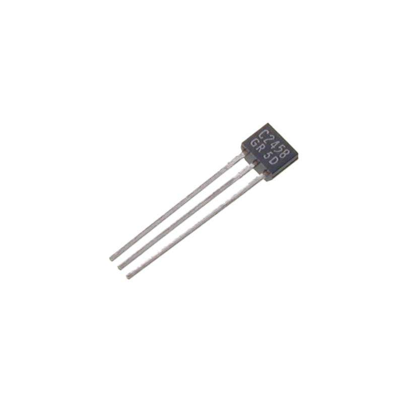
BTW, from the gut shot pic of the original pedal, the transistor looks like a Toshiba 2SC2458
View attachment 2762719
The shape of that transistor reminded me of transistors in my 70's Akai and Hitachi stereo gear.
-Frank
Crowella
Commercial User
- Feb 16, 2008
- 21,240
- 23,633
- Disclosures
- John K Custom Basses
If you do both the Tube Screamer type of feedback clipping AND the RAT type of clipping to ground, I suggest that you use anti-parallel LEDs across R9. This way if you throw both TS and RAT mode switches on at the same time, the signal hitting the RAT clipping will be large enough to clip.
Surface mount isn't so bad after a little practice.
-Frank
?
Uhm... so this would be an example of parallel to the resistor? :
Asymmetrical, but still parallel...
So antiparallel across resistor would be... hmm no online-diagrams of what I imagine it to be... something like either A or B?
Would A even clip properly?
If "B", would it matter if the diode pair are placed as above or should they be "between" C5 and R9?
?
Uhm... so this would be an example of parallel to the resistor? :
View attachment 2762920
Asymmetrical, but still parallel...
View attachment 2762921
So antiparallel across resistor would be... hmm no online-diagrams of what I imagine it to be... something like either A or B?
View attachment 2762918
Would A even clip properly?
If "B", would it matter if the diode pair are placed as above or should they be "between" C5 and R9?
This is considered an anti-parallel diode configuration:
The diodes are parallel, but conduct in opposite directions. This anti-parallel diode configuration would then be connected in parallel with the R9 resistor like the first diagram in your post. This is symmetrical diode clipping because the diodes have the same forward break-over voltage. If you have an additional diodes on either side that make the total break-over voltage different than the adjacent diode(s) total break-over voltage, then the clipping becomes asymmetrical. Using diodes of different types, like an LED and a germanium diode, will also be asymmetrical clipping because the two diodes have different break-over voltages. The LED is about 1.5V and a germanium is about 0.3V. Typical signal diodes are approx 0.7V.
-Frank
Thanks @boomertech.
I've only seen paired clipping diodes facing in opposite directions, but I'd never heard it called antiparallel before.
For that matter if there's more than one they seem to be facing opposite directions, for ex:
⊻⊼
⊻⊼
⊻⊼
So much to learn...
I've only seen paired clipping diodes facing in opposite directions, but I'd never heard it called antiparallel before.
For that matter if there's more than one they seem to be facing opposite directions, for ex:
⊻⊼
⊻⊼
⊻⊼
So much to learn...
Crowella
Commercial User
One of the fun things is mixing them all up with different ones and stacking on, using only one, etc. For those who want to dip into DIY and make something really simple, I would suggest the Bazz Fuss. That's a really good one to understand how the diodes work because they basically do all the work. Subbing them out, making it assymetrical, even using some old leaky Germanium transistors, it's good fun.

Good to have friends in high places...happened to mention that I regretted selling my JohnK Animato clone recently, and a month later...
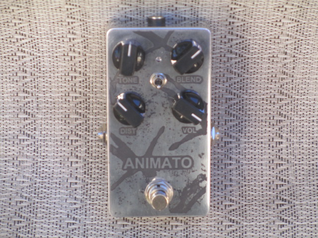
This one sounds even better than my old one. Sounds a bit more full in the lows without the blend than I remember the old one. Still needs the blend, I think, but it's awfully close to being able to work without it. And now that I have one of those Green Russian Big Muff reissues, I totally get why Chris from Muse loves to pair up an Animato and Muff. Man, does that sound great!
This pic does it no justice...it's much shinier and chromey than the old one, the lettering and artwork is much darker, and I think it may even be lighter in weight, but here it is anyway. Anyway, thanks to my good old friend JohnK, I am whole once again, and I shall never make that mistake again!
This one sounds even better than my old one. Sounds a bit more full in the lows without the blend than I remember the old one. Still needs the blend, I think, but it's awfully close to being able to work without it. And now that I have one of those Green Russian Big Muff reissues, I totally get why Chris from Muse loves to pair up an Animato and Muff. Man, does that sound great!
This pic does it no justice...it's much shinier and chromey than the old one, the lettering and artwork is much darker, and I think it may even be lighter in weight, but here it is anyway. Anyway, thanks to my good old friend JohnK, I am whole once again, and I shall never make that mistake again!
Crowella
Commercial User
Always thought John did a fantastic job including the Absolution artwork on his. I went a week without one at band practice (loaned to another band) and I missed it instantly. The combo with a Big Muff is really something special.
Finally got some more parts on the way to finish the existing stock that I have (probably about 10 units), I'd say a few weeks, because UPS shipping is pretty damn slow. In the meantime, working on a new revision with SMD parts, new external design because I do want to push some other pedals out too in the next few months and all that sort of stuff, might even finish that big muff like pedal too, once I get some more zzzzzz and rest.
Also, quick tidbit, I'm more than happy to help people with trying to fix their DIY ones but I too will have issues with supplying parts, I've had a few people message me with help on how to fix their kits (usually the Fuzz Dog boards), my first recommendation though to those that ask is to have a multimeter on hand to measure certain points and if you have the stuff, look up an "audio probe" to futher test the circuit.
Finally got some more parts on the way to finish the existing stock that I have (probably about 10 units), I'd say a few weeks, because UPS shipping is pretty damn slow. In the meantime, working on a new revision with SMD parts, new external design because I do want to push some other pedals out too in the next few months and all that sort of stuff, might even finish that big muff like pedal too, once I get some more zzzzzz and rest.
Also, quick tidbit, I'm more than happy to help people with trying to fix their DIY ones but I too will have issues with supplying parts, I've had a few people message me with help on how to fix their kits (usually the Fuzz Dog boards), my first recommendation though to those that ask is to have a multimeter on hand to measure certain points and if you have the stuff, look up an "audio probe" to futher test the circuit.
Crowella
Commercial User
Bumping to say I've got a few more for sale since I had some people message me here.
I had a bit more of a breadboard tinker and I had remembered just how much fun it was playing with the filtering on the first stage.
Also, because I feel adventurous, this is happening in a few weeks.
I had a bit more of a breadboard tinker and I had remembered just how much fun it was playing with the filtering on the first stage.
Also, because I feel adventurous, this is happening in a few weeks.
Crowella
Commercial User
Actually do have an update on it, thanks for reminding me!
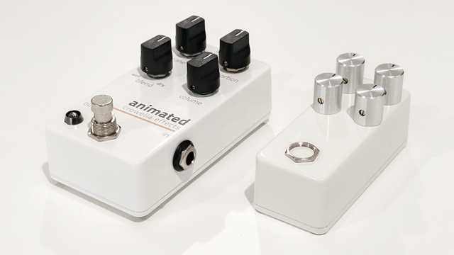
I sent files off today to have the (hopefully final) prototype done. I had to change the blend in it because the one used in the Animated is fine, in the Voskhod, it causes some feedback. My thought process was to go overkill with the clean blend, so I have done so.
Both pedals will have a few modifications too. Power supply is going on the board to make assembly a bit easier and I'm changing to mostly SMD parts because it could save considerable time to get boards mostly assembled before reaching me. A robot will do a soldering job substantially better than I could ever do but the prototypes are done by hand anyway, there not that small.
Also added the same original power filtering. The one in the original Animato was a bit overkill but I added it back in, in it's entirety plus a little extra which will help reduce more of the DC noise.
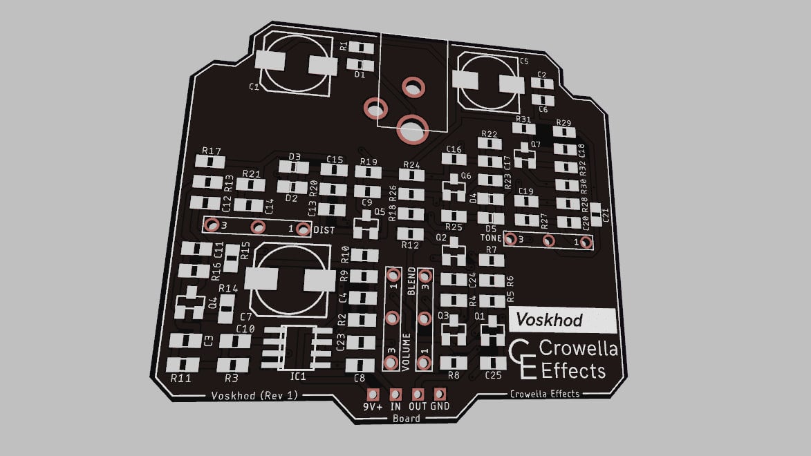
A part of me is debating what colour the outside should be for the Voskhod. It was going to follow the clean white aesthetic but I think I could get a little bit creative with it, while still following my "style guide". Something something taking these all seriously.
Aaaaand, one other thing. Working on a bass preamp to have nice cleans to an overdrive. It's fun so far.
I sent files off today to have the (hopefully final) prototype done. I had to change the blend in it because the one used in the Animated is fine, in the Voskhod, it causes some feedback. My thought process was to go overkill with the clean blend, so I have done so.
Both pedals will have a few modifications too. Power supply is going on the board to make assembly a bit easier and I'm changing to mostly SMD parts because it could save considerable time to get boards mostly assembled before reaching me. A robot will do a soldering job substantially better than I could ever do but the prototypes are done by hand anyway, there not that small.
Also added the same original power filtering. The one in the original Animato was a bit overkill but I added it back in, in it's entirety plus a little extra which will help reduce more of the DC noise.
A part of me is debating what colour the outside should be for the Voskhod. It was going to follow the clean white aesthetic but I think I could get a little bit creative with it, while still following my "style guide". Something something taking these all seriously.
Aaaaand, one other thing. Working on a bass preamp to have nice cleans to an overdrive. It's fun so far.
Crowella
Commercial User
So I went a bit silly and did end up making the nano one. I did make the power part of the PCB wrong so it'll need external wiring with a small power jack but it works 100%
Even did a Youtube cover with it today on the breadboard. Once I've boxed it up, it's probably going to be my touring pedal.
That all said, got the Voskhod and the new Animated prototype done, so I'm really happy they work too, even if they have the same issue with the power wiring. This is why they are prototypes.
Even did a Youtube cover with it today on the breadboard. Once I've boxed it up, it's probably going to be my touring pedal.
That all said, got the Voskhod and the new Animated prototype done, so I'm really happy they work too, even if they have the same issue with the power wiring. This is why they are prototypes.
Attachments

Crowella
Commercial User
Bump, only because a few people asked. Few months off while I wait for the cases to be painted up.

That looks awesome. Let us know when they are available for purchase!So I went a bit silly and did end up making the nano one. I did make the power part of the PCB wrong so it'll need external wiring with a small power jack but it works 100%


