• TalkBass has been independent since 1998. Add your voice.
    Create a free account to reply to discussions, view embedded media, and browse with fewer display ads.
    Join freeLog in
    Want zero display ads or expanded classifieds tools? Compare plans.

Specialized Holding Fixtures for Luthier Work

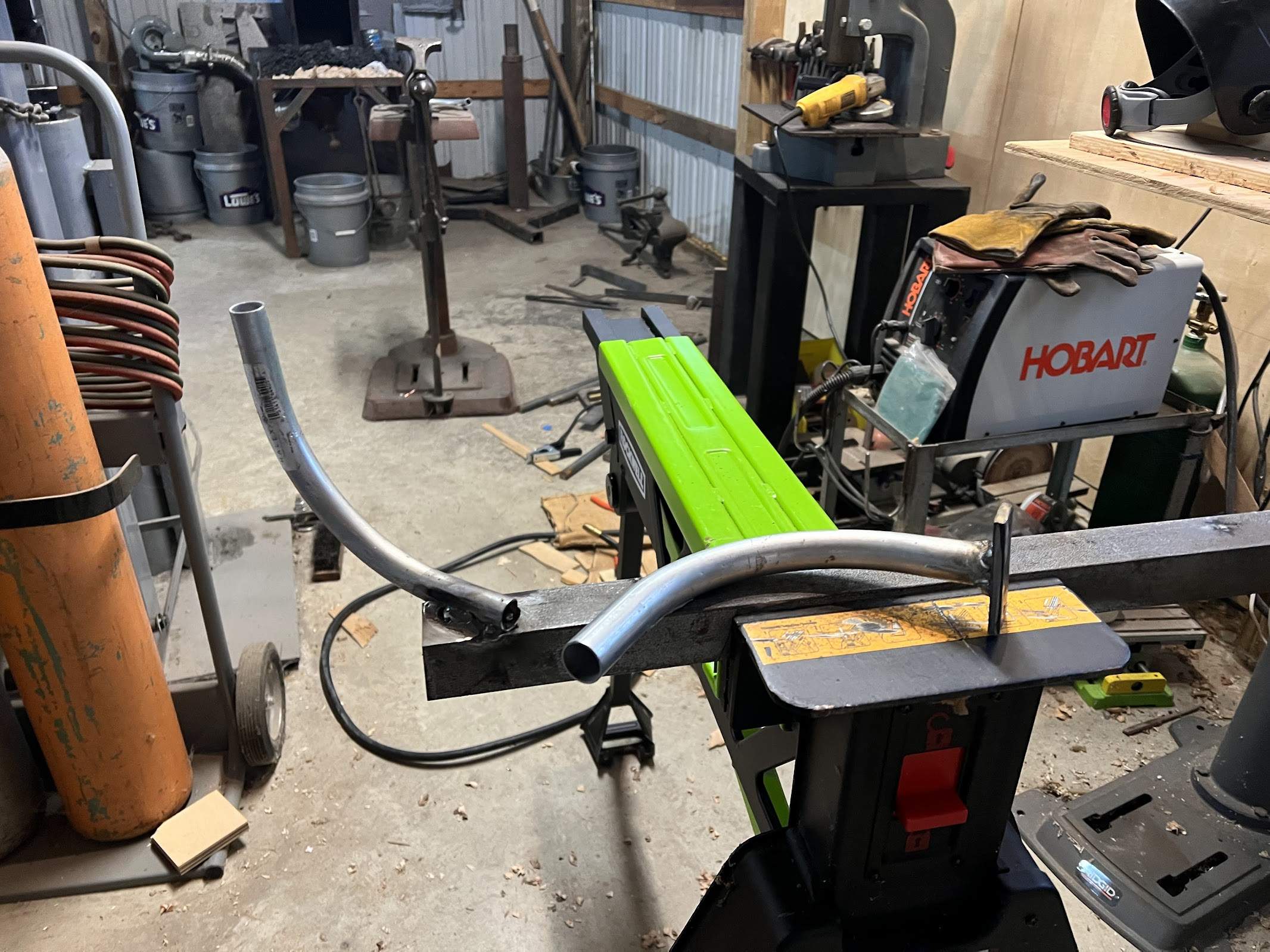
Here's my "quick and dirty" holder I made to hold my WBO bass. I've only made bolt-on necks before and this one is a headless neck-through, so I needed to come up with something different. There are three pieces. The first is a plate welded to a 1" conduit elbow, the second a 3/4" conduit elbow welded to a piece of angle iron:

IMG_2323.jpg


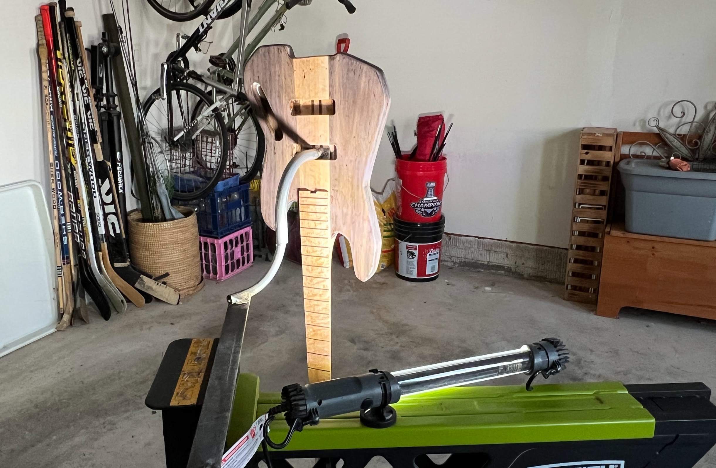
The 1" elbow on the plate gets screwed into the pickup route and slides over the 3/4" elbow clamped into my jawhorse for spraying:

IMG_2353.jpg

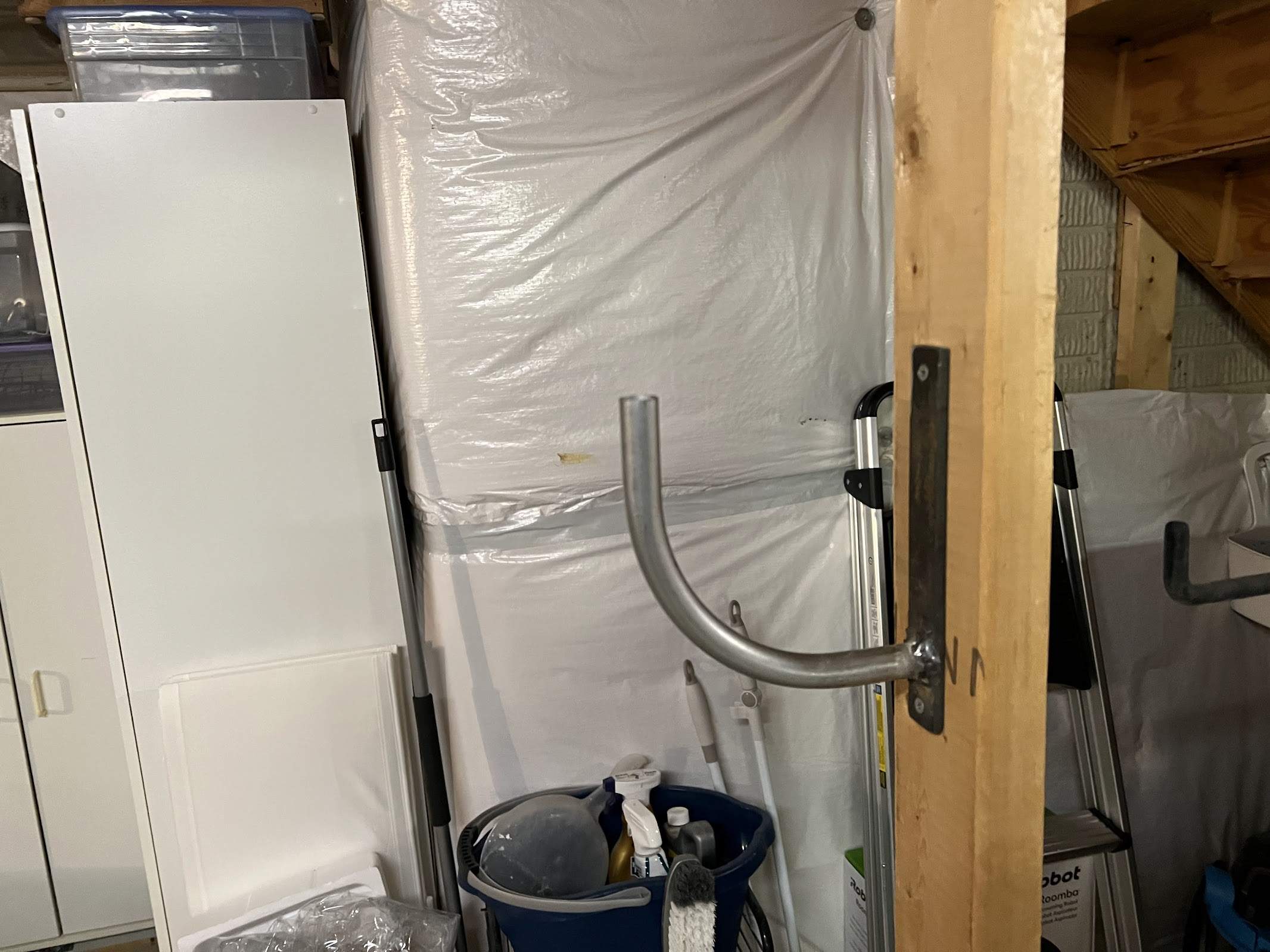
The third piece is is a 3/4" elbow welded to a plate that is screwed into a studwall in my basement. This allows the bass to hang without hogging up the garage:

IMG_2326.jpg

I think I'll call it my skyhook.
 
Here's my "quick and dirty" holder I made to hold my WBO bass. I've only made bolt-on necks before and this one is a headless neck-through, so I needed to come up with something different. There are three pieces. The first is a plate welded to a 1" conduit elbow, the second a 3/4" conduit elbow welded to a piece of angle iron:

View attachment 4993802

The 1" elbow on the plate gets screwed into the pickup route and slides over the 3/4" elbow clamped into my jawhorse for spraying:

View attachment 4993808
The third piece is is a 3/4" elbow welded to a plate that is screwed into a studwall in my basement. This allows the bass to hang without hogging up the garage:

View attachment 4993813
I think I'll call it my skyhook.

Very cool! A simple but effective design.

For those of you who don't have a steel fabrication shop handy, you can make similar style holding fixtures from electrical conduit, from the electrical department of your local box store. You can buy pre-bent 90 degree elbows, straight lengths, and fittings. Saw them with a hacksaw and put the parts together with the fittings.

The conduit isn't as sturdy as what JC76 built, but it's strong enough to work.
 
  • Like
Reactions: Rafar and JC76
The video was interesting to watch.

I now understand why I've seen so many import acoustic guitars that have bridge lift. If all the factories do it like that it's hard to believe any of them stay down past the warranty period.

I also noted that every step looks like the focus is minimizing any chance for glue squeeze out so there's minimal time spent on cleanup. All the gluing operations are done by application of the adhesive to only one side of the joint, even top and back plate edges. That's great for production and not so great for longevity of the instrument.
 
Last edited:
Do you want to see how fixtures help speed up work? You're not going to do this at home, but you might get some ideas.


That's a good thorough video tour, showing most of the manufacturing steps in great detail. And I think that's representative of most of the overseas factories that turn out thousands of low price guitars and basses.

Notice how their whole manufacturing process is mostly hand labor, but using special tools, gauges, fixtures and hard automation machines. Good old-fashioned '50's technology industrial engineering. Many of the fixtures and machines are similar to what we small builders use, but they just built a whole row of them. Stronger, out of steel, but the same idea as ours. The gluing fixtures were steel frames with pneumatic cylinders. Many of them had heaters built into the clamping pads; they are using heat-cure glue for speed. Lots of gluing fixtures in drum carousels. You can see that they invested heavily in reducing the time delay of the gluing operations.

There isn't much fancy robotics or CNC. They used a laser to cut out the tops and backs, but I couldn't see if it was CNC driven or a pattern-follower. Their neck shaping machine was a twin-head CNC router. We saw them step-cut the basic shape, but then they moved on. Didn't see how finely the cut the shape on that machine, or whether they just have some guy smooth it out on a drum sander.

Their fret slotting saw was a simple old-fashioned hard automation machine. A single blade, back and forth pneumatically, stopping on the positions on a hard cam. I'm surprised by that. I thought they would have invested in a gang saw, like Fender and most manufacturers use.

The frets are glued in, using a neat pneumatic tube tip. A guy hand-taps the frets in, quickly. They didn't show it, but I'm sure there's a Smash Leveling step in a big pneumatic press.

Tuner holes are drilled with a gang drill.

A cool pattern-following router rig is used to cut the neck pocket in the body, matching the actual neck for that instrument. That's pretty clever.

Related to this thread, note the painting hangers. Round tubes, screwed to the neck and body. And the spray booth isn't much bigger or more sophisticated than ours. They just built whole rows of drying racks.
 
I'm ignorant here. What's the difference between how they do it and how a craftsperson would do it?
It was hard to see, but it looked like they just scuffed the finish and glued the bridge to the finish instead of the wood. Same when they glued the fingerboard extension to the top. Normally you would completely remove the finish so you are gluing wood to wood.
 
  • Like
Reactions: Flamingo21
Back on the subject of Fixtures For Holding Necks While Carving Them:

I came up with an interesting new improvement to my Neck Horse, my floor-standing neck-holding fixture. I showed and described it back on Page 2. It's been a workhorse, literally, for many years.

The new idea was inspired by some of the neck-holding fixtures that you folks have made.

IMG_0354B.jpg


Here's the frame of the Neck Horse; the center plywood web, the two vise-like clamps at the ends, and the two triangular feet. The triangular feet bolt onto the center section. I can quickly remove them to store the Neck Horse more compactly.

The Neck Horse works very well, supporting the neck solidly while I do two-handed shaping with large files and tools. But...It's big and kind of in the way. When I slide it over near the woodworking bench, it can't get close to the bench, and I'm stepping around those feet.

I looked at some the neck-holding fixtures that you guys have made, and I liked the idea that they were mounted on the corner of the bench. But I liked the stability of having the Neck Horse sitting solidly on the floor. So....I thought about combining the two ideas......Make the Neck Horse quickly attach to the bench....

IMG_0355B.jpg


The modification was actually pretty simple. I took some measurements and laid out a rectangular hole in the middle of the plywood web. Drilled the corners and sawed it out with my scroll saw.....

IMG_0356B.jpg


And I took off the triangular legs......

IMG_0357B.jpg


I lift and set the Neck Horse over the vise.......

IMG_0358B.jpg


And tighten the vise. You can see how the wood right above the hole is at the right height to clamp in the vise, with the legs resting on the floor.

IMG_0359B.jpg


And there it is....Clamped in the vise, it's very solid and locked in a comfortable working position. I can reach all around it, my rack of carving tools is right there, and I'm not tripping over those triangular feet.

IMG_0360B.jpg


This is a significant improvement to the function of the Neck Horse. And, when I'm done with it, I can loosen the vise, lift it off, and store it in a narrower space. But, I can always bolt the triangular feet back on if I want to work with it free-standing in an open area.

This is a way to improve your own neck-holding fixtures. Make the fixture clamp in the vise, but with legs that straddle the vise and rest on the floor.
 
Excellent permutation of the older version of the neck horse!

I thought about simply slotting the end of my bench to make the corner mount neck jig in post#10 almost instantly mountable or removable, but in reality it only takes about 10 seconds to remove the quick spin knob that retains it, so I didn't bother.

My jig has been seeing a fair amount of use lately for guitar necks.

3JzaSEY.jpg
 
Last edited:
I probably posted this in the original build thread, but here's my entry-level neck carving jig. One thing that's notable is that the tight radius fingerboard on my upright bass build would not sit flat on the top of the beam, so I added a shallow V to stop it rocking. Also, ratchet straps are very versatile for clamping odd shapes without cauls.
IMG_4906D.JPG IMG_4901D.JPG
 
I'm starting a thread about holding fixtures. These are home-made jigs and fixtures that we build to hold instrument parts steady while we work on them. One of the tough parts about Luthier work is that musical instrument parts are mostly all curved and shaped and funny looking. They are hard to hold on to when you need to apply some muscle to them.

Holding fixtures can be temporary, or they can be permanent. Stored on a shelf and pulled out for use many times.

I'll show you some of my most useful ones, and I welcome all of you to show what you've built. Crude setups or finished tooling.

I'll start out with one I just made an hour ago. It's a permanent holding fixture for holding the heel of a neck in a drill press or milling machine vise. Accurately and securely, and instant setup. I should have made this a long time ago. For years, I've been fumbling around with wedges and wood scraps and shims, trying to lock a neck heel into the milling machine vise.....I decided to stop and make up a decent holding fixture.

View attachment 4942005

This type of holding fixture is basically a pair of custom-shape wooden vise jaws. They are made to set down into a vise. The neck fits into the wooden jaws, and the vise tightens the jaws on the sides of the neck heel.

View attachment 4942006

The two jaws are kept aligned by a pair of pins. The pins are short lengths of 3/16" stainless steel rod, cutoffs from making truss rods. But they could be any steel or aluminum rod stock or pins. They are a sliding fit in matched holes in the jaws.

The jaws are quickly made from scraps of maple. The bottom blocks are cut from 6/4 (1 1/4") stock. The top wedge blocks are 3/4" thick.

I designed this fixture to fit a vise whose jaws are 6" wide x 2" high. That's common for 6" milling machine vises. A guitar or bass neck heel is normally about 3/4" thick. I sized the maple blocks so that the top surface of the heel would end up about even with the top of the vise jaws.

View attachment 4942007

I cut the wedges based on the measurements from the taper of common necks. Most necks taper 1/8" over 6", so that's how I made this fixture. But the jaws have some freedom of angular movement. They will still clamp if the neck's taper is slightly different.

I also put in a wood dowel end stop pin on one side. The heel of the neck will sit solidly against it, so it won't slip in the tapered jaws.

View attachment 4942008

And here it is in use, clamping a guitar neck heel in the mill vise. The neck is clamped securely between smooth wood surfaces, to minimize any marks on the finish, as I preform some surgery on it.

View attachment 4942009

This neck is from an expensive guitar built by my friend Bill Asher. It had a broken truss rod, unfortunately. I'm about to machine the heel to take one of my newer double-acting spoke wheel head assemblies.

It took me about 30 minutes to make up this holding fixture. And now it's a permanent tool to be used for many years.

I have other truss rod replacement jobs waiting in line. Including two Wals. And I really don't want to damage those necks....
Thanks for sharing/starting this thread Bruce!
This concept could certainly help my situation.

My regular bench vises stick out to far and are at a height that is a danger zone :)

So, I took to the portable Moxon vise craze, and built one with two veneer clamps and some poplar.

MyMoxon1.jpeg

MyMoxon2.jpeg


All looking good holding down a neck shape...

However....

MyMoxonRacking.jpeg


This kind of racking eventually makes holding this down ¯\_(ツ)_/¯

So, I thought I could either place some 1/4 20 threaded rod thru the bottom corners and have them serve as stand off/stops
like on some of the router planing fixtures I've made (based on your designs of course :)).

Or use something like you made above to fit into the Moxon...

What I like about this vise I made is the veneer handles don't protrude out toward my body so far (like other moxon designs).
That being the case, I think putting the 1/4 20 threaded rod thru the black side, and pushing out on to the outer vise face.

Anyway, lots of options, and again thanks for sharing :)

Adam
 
  • Like
Reactions: rwkeating
Thanks for sharing/starting this thread Bruce!
This concept could certainly help my situation.

My regular bench vises stick out to far and are at a height that is a danger zone :)

So, I took to the portable Moxon vise craze, and built one with two veneer clamps and some poplar.

View attachment 7023149
View attachment 7023148

All looking good holding down a neck shape...

However....

View attachment 7023150

This kind of racking eventually makes holding this down ¯\_(ツ)_/¯

So, I thought I could either place some 1/4 20 threaded rod thru the bottom corners and have them serve as stand off/stops
like on some of the router planing fixtures I've made (based on your designs of course :)).

Or use something like you made above to fit into the Moxon...

What I like about this vise I made is the veneer handles don't protrude out toward my body so far (like other moxon designs).
That being the case, I think putting the 1/4 20 threaded rod thru the black side, and pushing out on to the outer vise face.

Anyway, lots of options, and again thanks for sharing :)

Adam

Hey Adam;

Looks cool! A benchtop custom Luthier's Neck Vise. It looks good and solid overall, but yes, you need to add something to stop the racking/tilting of the moving jaw. There are several ways to do this.

One way is to use jacking screws, like you've seen on many of my routing fixtures. A pair of 6" long full-threaded bolts located down under the two vise screws, near the bottom. They come in from the back of the stationary jaw and thread through big T-nuts in the front face of the stationary jaw. The tip of the bolt presses against the bottom of the moving jaw, keeping it from tipping. For a fairly large vise like this, I'd recommend 5/16"-18 ot 3/8"-16 bolts. Your vise screws are pretty sturdy and can apply a few hundred pounds of force. The jacking screws are a simple solution which will work well. But they are somewhat annoying to have to re-adjust them every time you put a different size object in the vise.

A second solution is to use spacer blocks. Chunks of wood or metal that set down into the bottom of the jaws, under the vise screws.

IMG_0692B.jpg


Here's an example. This is a small, special purpose wooden vise that I made for my buffing bench. It's made to clamp onto the 3/4" square aluminum tubes that I use for my body and neck holders.

IMG_0694B.jpg


The vise is very simple construction, two big blocks of 8/4 maple and a rectangle of plywood. The left block is screwed down to the plywood base. The right block slides freely. The vise screw is a chunk of 1/4-20 threaded rod with an aluminum T-handle. There's a 1/4-20 T-nut set into the back side of the moving jaw.

Between the jaws, down at the bottom, is a chunk of 3/4" aluminum. It's just resting in there, not a permanent part. It's the same width as the part I'm normally clamping in the vise, the painting holder. That spacer block keeps the moving jaw from tipping. The vise can clamp very tightly.

You can put spacer blocks like this in your vise. For example, to clamp that tapered neck template, all you need is a scrap of wood of the same width and taper. Set it down between the jaws, at the bottom. Add some pins or tabs or something so it doesn't fall out the bottom. Tighten the vise screws, and it will clamp hard, without the jaw tilting.

The idea is that you have a small collection of spacer blocks to match the sizes of things that you commonly clamp in the vise. Set them in there and lift them out; change in seconds.

You can also combine the idea of the spacer blocks with the jacking screws. Have a few spacer blocks for the common size things, and/or adjust in the jacking screws for the oddball things.

The fancy way to solve the tilting-jaw problem is to use sliding bars, Common woodworking vises use two round steel bars on either side of the vise screw, The bars are rigidly attached to the moving jaw, and slide in bushings in the stationary jaw. Very strong, but more complicated to make up for your own vise.

Here's a simpler way to do it using rectangular aluminum bars.

IMG_9775B.jpg


This is a special fixture that I made up to hold straight neck-lam strips while I pass them through my SPRP machine. It's a long, low profile vise, similar to yours. The right side jaw is stationary, screwed down to the base. The left side jaw moves, sliding on the base, and is clamped by three T-handle screws. T-nuts on the back side of the stationary jaw.

IMG_9776B.jpg


Here's the moving jaw pulled out. There are two 1/4" x 1" aluminum bars rigidly attached to the moving jaw. They keep the jaw from tilting as the vise is tightened. There are also two guide pins with springs. They cause the jaws to open by themselves when the screws are loosened. A time saver in production.

IMG_9777B.jpg


Here's the moving jaw flipped upside-down. The bar needs to be rigidly attached to the jaw. I extended the bar through the jaw, bolted to the two MDF blocks. The whole bottom surface of the bar rests on the base.

IMG_9778B.jpg


At the stationary jaw side, the bar slides between these two fixed blocks, I've allowed a small gap on either side of the bar, between the blocks. This allows the moving jaw to go a little bit out of parallel, if I want to clamp a strip that's tapered. But the plywood block between the MDF blocks sits down on top of the bar, no real clearance, a nice sliding fit.

You could do something like this to your vise. It's more work to build, but there's no extra adjusting or swapping blocks.
 
Last edited:
Hey Adam;

Looks cool! A benchtop custom Luthier's Neck Vise. It looks good and solid overall, but yes, you need to add something to stop the racking/tilting of the moving jaw. There are several ways to do this.

One way is to use jacking screws, like you've seen on many of my routing fixtures. A pair of 6" long full-threaded bolts located down under the two vise screws, near the bottom. They come in from the back of the stationary jaw and thread through big T-nuts in the front face of the stationary jaw. The tip of the bolt presses against the bottom of the moving jaw, keeping it from tipping. For a fairly large vise like this, I'd recommend 5/16"-18 ot 3/8"-16 bolts. Your vise screws are pretty sturdy and can apply a few hundred pounds of force. The jacking screws are a simple solution which will work well. But they are somewhat annoying to have to re-adjust them every time you put a different size object in the vise.

A second solution is to use spacer blocks. Chunks of wood or metal that set down into the bottom of the jaws, under the vise screws.

View attachment 7024288

Here's an example. This is a small, special purpose wooden vise that I made for my buffing bench. It's made to clamp onto the 3/4" square aluminum tubes that I use for my body and neck holders.

View attachment 7024289

The vise is very simple construction, two big blocks of 8/4 maple and a rectangle of plywood. The left block is screwed down to the plywood base. The right block slides freely. The vise screw is a chunk of 1/4-20 threaded rod with an aluminum T-handle. There's a 1/4-20 T-nut set into the back side of the moving jaw.

Between the jaws, down at the bottom, is a chunk of 3/4" aluminum. It's just resting in there, not a permanent part. It's the same width as the part I'm normally clamping in the vise, the painting holder. That spacer block keeps the moving jaw from tipping. The vise can clamp very tightly.

You can put spacer blocks like this in your vise. For example, to clamp that tapered neck template, all you need is a scrap of wood of the same width and taper. Set it down between the jaws, at the bottom. Add some pins or tabs or something so it doesn't fall out the bottom. Tighten the vise screws, and it will clamp hard, without the jaw tilting.

The idea is that you have a small collection of spacer blocks to match the sizes of things that you commonly clamp in the vise. Set them in there and lift them out; change in seconds.

You can also combine the idea of the spacer blocks with the jacking screws. Have a few spacer blocks for the common size things, and/or adjust in the jacking screws for the oddball things.

The fancy way to solve the tilting-jaw problem is to use sliding bars, Common woodworking vises use two round steel bars on either side of the vise screw, The bars are rigidly attached to the moving jaw, and slide in bushings in the stationary jaw. Very strong, but more complicated to make up for your own vise.

Here's a simpler way to do it using rectangular aluminum bars.

View attachment 7024317

This is a special fixture that I made up to hold straight neck-lam strips while I pass them through my SPRP machine. It's a long, low profile vise, similar to yours. The right side jaw is stationary, screwed down to the base. The left side jaw moves, sliding on the base, and is clamped by three T-handle screws. T-nuts on the back side of the stationary jaw.

View attachment 7024318

Here's the moving jaw pulled out. There are two 1/4" x 1" aluminum bars rigidly attached to the moving jaw. They keep the jaw from tilting as the vise is tightened. There are also two guide pins with springs. They cause the jaws to open by themselves when the screws are loosened. A time saver in production.

View attachment 7024319

Here's the moving jaw flipped upside-down. The bar needs to be rigidly attached to the jaw. I extended the bar through the jaw, bolted to the two MDF blocks. The whole bottom surface of the bar rests on the base.

View attachment 7024320

At the stationary jaw side, the bar slides between these two fixed blocks, I've allowed a small gap on either side of the bar, between the blocks. This allows the moving jaw to go a little bit out of parallel, if I want to clamp a strip that's tapered. But the plywood block between the MDF blocks sits down on top of the bar, no real clearance, a nice sliding fit.

You could do something like this to your vise. It's more work to build, but there's no extra adjusting or swapping blocks.


Yes!

Lots of great ideas Bruce. Honestly, the jacking screws option wasn't my first choice. I find it to be a bit more time consuming than I'd like. This last concept with the bars at the bottoms I like. Was thinking that I might be able to just drill two 3/8" holes thru the face and base clamps and simply run aluminum bar thru them. Or some horizontal 1" bar thru slots. Mainly just keeping the bottoms from tilting up. Not really needing a tight fit to accomplish the up tilt. Or something along these lines (bottom section but horizontal with a bolt or something simple to hold it in place....
Screenshot 2024-09-07 at 10.21.16 PM.png
 
Was thinking that I might be able to just drill two 3/8" holes thru the face and base clamps and simply run aluminum bar thru them. Or some horizontal 1" bar thru slots. Mainly just keeping the bottoms from tilting up. Not really needing a tight fit to accomplish the up tilt.

If you use the sliding bar idea, the bars need to be bigger than 3/8". You'd bend them, seriously. There's a lot of force down there in the bottom of the vise. The moving jaw will be trying to bend the bar upward. A round sliding bar would need to be about 3/4" diameter aluminum. That's why I went for the rectangular aluminum bar 1" tall x 1/4" wide.

And don't make the fit at the sliding side too loose. Any clearance there becomes a small angle of the moving jaw. And that means less clamping power up at the top. Your neck blank will slip easier if the jaws aren't parallel.
 
Here's my entry in the category of Improvised Holding Fixtures for Neck-Thru Basses;

IMG_0774B.jpg


Yep, the seat of a rolling office chair provides a soft support for the body of this Rickenbacker while I'm shaping its headstock in the vise. It works very well.

IMG_0775B.jpg


I keep that chair adjusted low, a few feet away. I rest the body on it while I'm holding the neck and doing hand detail sanding of the headstock.
 
Last edited:
Here's a quick video showing my most often used workbench vise / holding aids. I'm posting this because it might be of interest to see my solution for instantly adjusting the bottom of the leg vise so it's parallel to the thickness of the work. I'm sure the same idea could be applied to the Moxon-type vises here that have the excessive tilt problem.

This video was made mostly to show how the leg vise is made, but the video for the building of the entire bench was posted back in post #17 in this topic.

I should post my Moxon-style vise, too. You guys probably know my solutions for making stuff "cheap and easy" would apply to that, too! :)


Latest posts