• TalkBass has been independent since 1998. Add your voice.
    Create a free account to reply to discussions, view embedded media, and browse with fewer display ads.
    Join freeLog in
    Want zero display ads or expanded classifieds tools? Compare plans.

Any DIY pedal builders on TB? Strut your stuff!

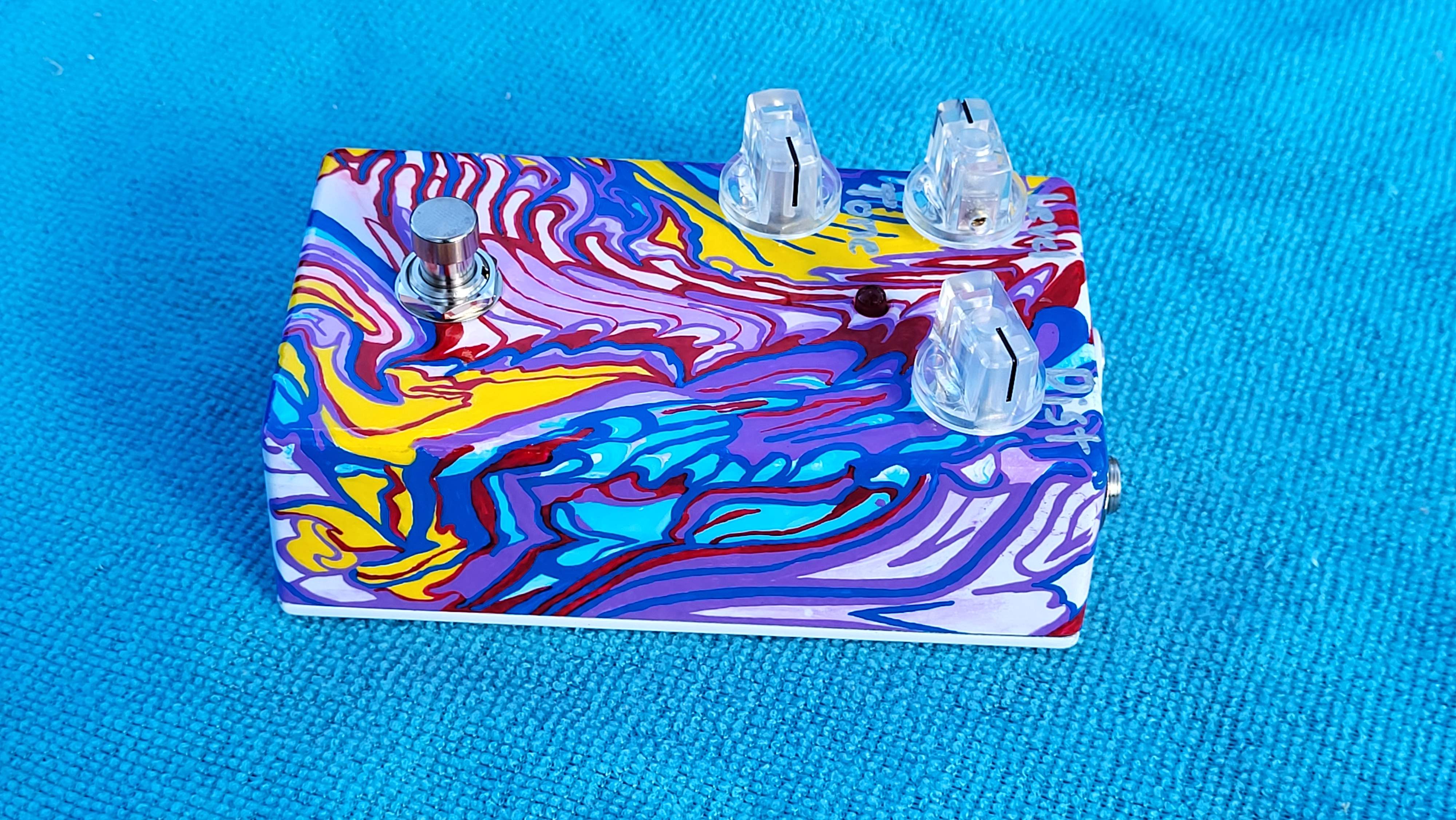
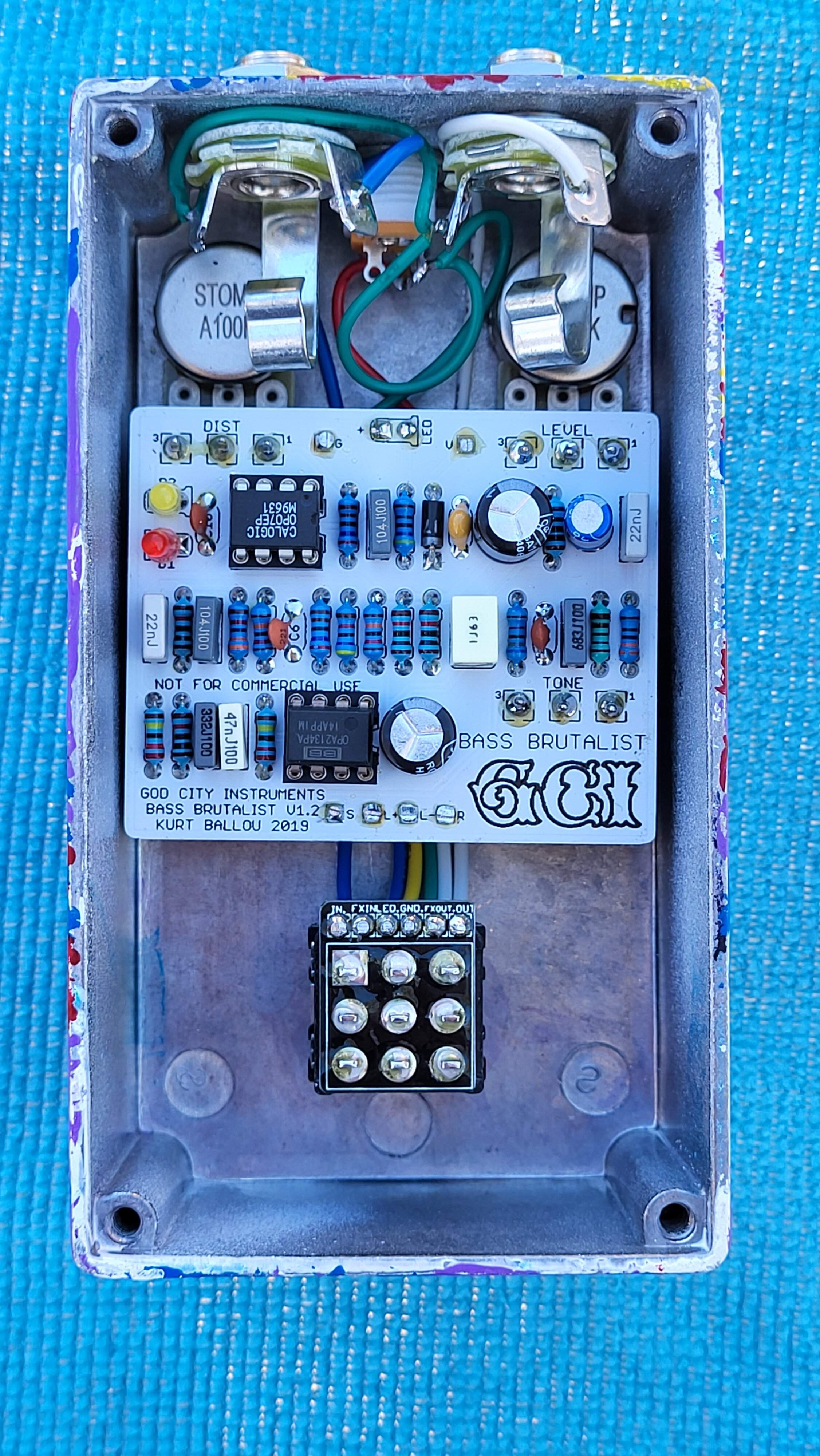
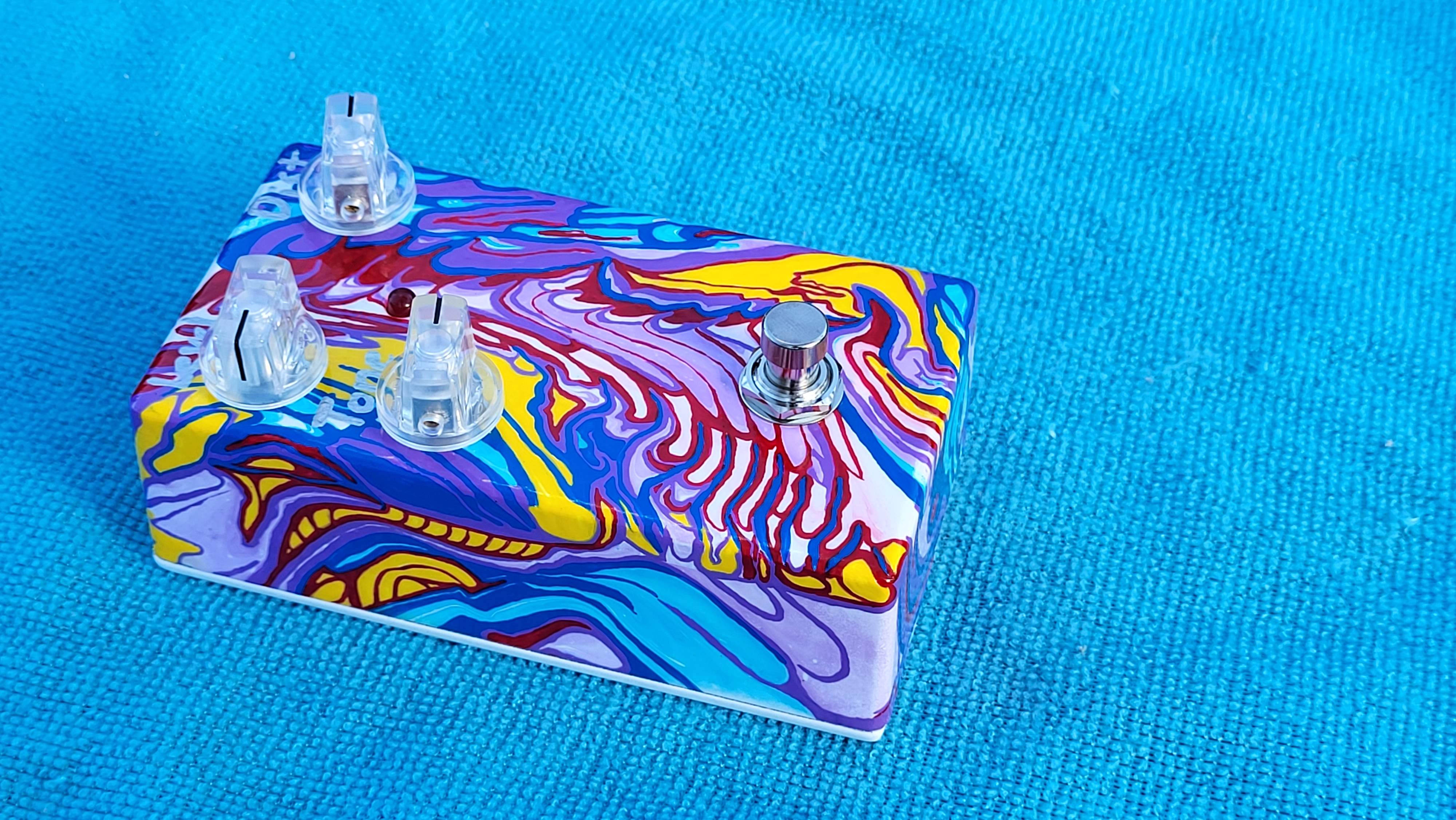
This is God City Instruments - Bass Brutalist. Better than any average rat distortion, a super rat!
Started with a high-gloss white base coat thinking I was going to brush on a pattern, but then changed my mind and went with a dipped paint scheme. The dipped paint didn't adhere well to the gloss coating, so I went back to painting with brushes. I painted over the faint colors and patterns with brushes and added patterns where there weren't any. Probably my most time consuming paint job yet. Painted one color at a time stretched out over 6 weeks while I waited on my next projects to arrive.

20221119_134835.jpg


20221119_134900.jpg


20221119_134927.jpg


20221119_133538.jpg
 
Just finished up. Full bass mods. Triumvirate V2 Standard soft bypass. The regular guitar version sounds good on bass but this takes it one step further. I’m not sure what the bass freq is set at but there is substantially more with the bass mods. The bass mods are really only changing the values of a few of the trim pots.
Happy Thanksgiving,
Matt
8D1937F1-0B12-475C-B34E-96FF885FD71F.jpeg
3F5D5290-0571-460E-8DA9-ABC4CD6D2C5C.jpeg
CE17BD44-8A74-4171-A777-BDF7FFAF6B78.jpeg
7D0025F2-AD7E-42D4-8045-CF5CAB29F479.jpeg
 
Nice job. What is the freq set / fixed at? This could be a very useful tool.
Just under 30Hz, measured. I usually do my variable ones with a sweep range from about 25-125Hz, and the same board will work fine for either format.
 
27002496[/URL], member: 352126"]do you by chance know of one with a variable sweep?

@fdeck has published the schematic for his very popular v3, which is more than just a basic HPF though: hpftechllc - HPF-Pre Series 3 technical info

And then my open source one will be officially released by late December, keep on eye on my long thread in the Pickups & Electronics forum. It’ll require hand soldering relatively large format surface mount parts, but I’m working on finding someone to do a board layout for a more beginner oriented DIY version as well.
 
@fdeck has published the schematic for his very popular v3, which is more than just a basic HPF though: hpftechllc - HPF-Pre Series 3 technical info

And then my open source one will be officially released by late December, keep on eye on my long thread in the Pickups & Electronics forum. It’ll require hand soldering relatively large format surface mount parts, but I’m working on finding someone to do a board layout for a more beginner oriented DIY version as well.
You said some of my favorite words, hand soldering surface mount parts
 
@fdeck has published the schematic for his very popular v3, which is more than just a basic HPF though: hpftechllc - HPF-Pre Series 3 technical info

And then my open source one will be officially released by late December, keep on eye on my long thread in the Pickups & Electronics forum. It’ll require hand soldering relatively large format surface mount parts, but I’m working on finding someone to do a board layout for a more beginner oriented DIY version as well.
I looked at your boards, and I think hand soldering wouldn't be too bad, with some instructions. I don't know your technique. I'm using a lot more surface mount for my day job. My technique is to start with a little blob of solder on just one pad for each part. Then I hold the part with a tweezers in one hand, and melt it into that blob with the other. Once all of the parts are in place, I go around and solder all of the remaining pads. This gives me a chance to re-position any ones that I'm not happy with, before committing.

I'm helping some beginners in my work group get started, and I don't really think the bigger surface mount footprints are any harder than through-hole soldering.

With some instructions on the sequence of parts, someone with at least a bit of soldering practice could probably do it. You could even leave some practice pads on the board -- parts that don't do anything. Lay the IC's first, then the low profile parts (R's and C's), then finally the tall parts and through-hole stuff.

For hand soldering, my take is that the best thing you can do is just space the parts out more. The boards will cost a tiny bit more, but it's money well spent if it reduces the risk of a failed project.

I'm really impressed! Maybe I'll fully open-source my next thing. The only problem is that I use non mainstream layout software, but Gerbers are Gerbers.
 
I looked at your boards, and I think hand soldering wouldn't be too bad, with some instructions. I don't know your technique. I'm using a lot more surface mount for my day job. My technique is to start with a little blob of solder on just one pad for each part. Then I hold the part with a tweezers in one hand, and melt it into that blob with the other. Once all of the parts are in place, I go around and solder all of the remaining pads. This gives me a chance to re-position any ones that I'm not happy with, before committing.

I'm helping some beginners in my work group get started, and I don't really think the bigger surface mount footprints are any harder than through-hole soldering.

With some instructions on the sequence of parts, someone with at least a bit of soldering practice could probably do it. You could even leave some practice pads on the board -- parts that don't do anything. Lay the IC's first, then the low profile parts (R's and C's), then finally the tall parts and through-hole stuff.

For hand soldering, my take is that the best thing you can do is just space the parts out more. The boards will cost a tiny bit more, but it's money well spent if it reduces the risk of a failed project.

I'm really impressed! Maybe I'll fully open-source my next thing. The only problem is that I use non mainstream layout software, but Gerbers are Gerbers.

Hey Francis, thanks for that feedback! I use the same tacking method myself. One thing I do to make hand soldering easier is to use slightly extended pads, which my free open source layout software KiCAD already includes in some of the footprint libraries. I've refined those footprints myself and some actual pro SMT techs like @AudioTaper have done some test builds for me and reported positively on that. And since hand soldering film caps can often be pretty problematic I've just stuck with through hole parts for all the caps. 1206 resistors are very easy to hand solder for me by now, so the SMD opamps are typically the only thing that I need to give a little extra attention to. I started off doing double sided boards with smaller components before my building skills were quite good enough, reliability suffered and rework was seriously unfun.

I've seen SMT practice boards on eBay and I think that's a great way to get some soldering chops up before throwing money at fully functional builds. I've also tested some really cheap SOIC-8 opamps from Tayda Electronics and have been thinking about recommending them for first builds, because wrecking a 13 cent part presumably won't bug most of us as much as killing a 3 or 10 dollar one. ;)

I want to commend you for all the DIY friendly posts over the years too, I think we all win from helping each other out when we can.
 
I looked at your boards, and I think hand soldering wouldn't be too bad, with some instructions. I don't know your technique. I'm using a lot more surface mount for my day job. My technique is to start with a little blob of solder on just one pad for each part. Then I hold the part with a tweezers in one hand, and melt it into that blob with the other. Once all of the parts are in place, I go around and solder all of the remaining pads. This gives me a chance to re-position any ones that I'm not happy with, before committing.

I'm helping some beginners in my work group get started, and I don't really think the bigger surface mount footprints are any harder than through-hole soldering.

With some instructions on the sequence of parts, someone with at least a bit of soldering practice could probably do it. You could even leave some practice pads on the board -- parts that don't do anything. Lay the IC's first, then the low profile parts (R's and C's), then finally the tall parts and through-hole stuff.

For hand soldering, my take is that the best thing you can do is just space the parts out more. The boards will cost a tiny bit more, but it's money well spent if it reduces the risk of a failed project.

I'm really impressed! Maybe I'll fully open-source my next thing. The only problem is that I use non mainstream layout software, but Gerbers are Gerbers.

I like to have the part in place with tweezers and have a small blob on the iron tip. Tack one side (or leg) check alignment and give it a second to cool. Then tack the other. Once everything looks good, I go back and add liquid flux and solder to get a nice fillet.

One thing that I would add for less experienced folks is to check what's around the parts. They might have to install certain components first or last due to other parts in close proximity.

Hey Francis, thanks for that feedback! I use the same tacking method myself. One thing I do to make hand soldering easier is to use slightly extended pads, which my free open source layout software KiCAD already includes in some of the footprint libraries. I've refined those footprints myself and some actual pro SMT techs like @AudioTaper have done some test builds for me and reported positively on that. And since hand soldering film caps can often be pretty problematic I've just stuck with through hole parts for all the caps. 1206 resistors are very easy to hand solder for me by now, so the SMD opamps are typically the only thing that I need to give a little extra attention to. I started off doing double sided boards with smaller components before my building skills were quite good enough, reliability suffered and rework was seriously unfun.

I've seen SMT practice boards on eBay and I think that's a great way to get some soldering chops up before throwing money at fully functional builds. I've also tested some really cheap SOIC-8 opamps from Tayda Electronics and have been thinking about recommending them for first builds, because wrecking a 13 cent part presumably won't bug most of us as much as killing a 3 or 10 dollar one. ;)

I want to commend you for all the DIY friendly posts over the years too, I think we all win from helping each other out when we can.

The elongated pads do make it a breeze. And it looks nice :thumbsup:
Screenshot_20221124-015217_Gallery.jpg
 
Hey Francis, thanks for that feedback! I use the same tacking method myself. One thing I do to make hand soldering easier is to use slightly extended pads, which my free open source layout software KiCAD already includes in some of the footprint libraries. I've refined those footprints myself and some actual pro SMT techs like @AudioTaper have done some test builds for me and reported positively on that. And since hand soldering film caps can often be pretty problematic I've just stuck with through hole parts for all the caps. 1206 resistors are very easy to hand solder for me by now, so the SMD opamps are typically the only thing that I need to give a little extra attention to. I started off doing double sided boards with smaller components before my building skills were quite good enough, reliability suffered and rework was seriously unfun.

I've seen SMT practice boards on eBay and I think that's a great way to get some soldering chops up before throwing money at fully functional builds. I've also tested some really cheap SOIC-8 opamps from Tayda Electronics and have been thinking about recommending them for first builds, because wrecking a 13 cent part presumably won't bug most of us as much as killing a 3 or 10 dollar one. ;)

I want to commend you for all the DIY friendly posts over the years too, I think we all win from helping each other out when we can.
Nice idea about the SMT pads. I did a similar thing with a TSSOP part. Among other things, a bit of extra land on pads gives some more surface area for the soldering iron to make good thermal contact.

Way long ago when I etched my own boards, I also discovered that big pads were more friendly to hand soldering for through-hole parts. Among other things, a bigger pad means more glue holding it down, so it can take a bit more heat before lifting off. It's high temperature glue, but it's still glue.

And while I'm thinking of it, if you put the through-hole parts on the other side, then you can still get in with your soldering iron to make repairs on the surface mount side.
 
Here’s one I did awhile back. I know , pretty lame name and graphics but that’s not my strong point.
This is a clone of a very well know muff and it uses real Russian diodes in place of what the original has. I ordered them from Ukrain , they took a few months to arrive. Even if they didn’t arrive I thought of it as a donation, them arriving was just a bonus.
I had to do a mod on the input and R18 to use the muff board I already had to make this version work. It sounds big and fat, definitely no low end loss. I have since had proper pcbs made of this version. I had an Amazon bypass pcb laying around so I used it up on this.
Matt
7D76EC60-0489-4F74-9C1A-755FF55BA585.jpeg
E3D35AC2-48A9-47EB-97E5-4BB2B7B54CCE.jpeg
 

Attachments

  • CAA57FA2-9BCB-42F4-A633-1F702F557B0E.jpeg
    CAA57FA2-9BCB-42F4-A633-1F702F557B0E.jpeg
    657.1 KB · Views: 18
@fdeck @Passinwind @AudioTaper Thanks for contributing to what is now my favorite TB thread
I agree and would like to add a couple to the list @johnk_10 @disssa and G.Bisson @Feral Feline @boomertech @Fuzzonaut . There are many more and if I left you out please dont be offended I learned of these guys on several other message boards and they are along with the above mentioned Top Notch contributors. I have learned alot and became friends with a few of them. Their willingness to help and offer years of expertise is beyond commendable. So along with you I would like to give a big THANK YOU. And you can't forget the one that started the thread @SubHuman . This is by far my favorite thread on TB along with the classifieds, lol.
Matt
 
I like to have the part in place with tweezers and have a small blob on the iron tip. Tack one side (or leg) check alignment and give it a second to cool. Then tack the other. Once everything looks good, I go back and add liquid flux and solder to get a nice fillet.

One thing that I would add for less experienced folks is to check what's around the parts. They might have to install certain components first or last due to other parts in close proximity.


The elongated pads do make it a breeze. And it looks nice :thumbsup:
View attachment 4883441
That is some beautiful soldering. What kind of tip are you guys using? I use a very small chisel tip but if there’s something better I’m open to suggestions. Also what temp do you like. I know some of those SMD parts don’t like high heat, don’t ask how I know, lol.
 
That is some beautiful soldering. What kind of tip are you guys using? I use a very small chisel tip but if there’s something better I’m open to suggestions. Also what temp do you like. I know some of those SMD parts don’t like high heat, don’t ask how I know, lol.
I'm using a Weller WD2M station (picked up a used one on ebay) which has the quick change tips.
Left to right
RT3, 1.3mm
RT4, 1.5mm
RT8, 2.2mm
20210413_172800.jpg


I use the RT4 for most things, temp is 650°F with Kester 63/37 285 flux core and type 197 liquid flux. Fume extractor is a Hakko 493.
The larger tips are great for larger SMT packs - flux it up and drag a bead of solder across the leads. Sometimes I have to touch up the last one. Clean with electronics grade isopropyl alcohol.

Heres the 100-pin quad pack off of my IPC practice board
20200205_190923.jpg
 
That is some beautiful soldering. What kind of tip are you guys using? I use a very small chisel tip but if there’s something better I’m open to suggestions. Also what temp do you like. I know some of those SMD parts don’t like high heat, don’t ask how I know, lol.

Hakko 888 here. I have at least a dozen tips in total, but these three get most of the love for SMD soldering:

1mm elliptical

upload_2022-11-25_11-3-1.jpeg


1.2mm screwdriver

upload_2022-11-25_11-4-6.jpeg


0.5mm conical


upload_2022-11-25_11-2-12.jpeg


I mostly use Kester 63/37 type 44 and rarely bother with liquid rosin, and often go with 725-750 degrees F in that case. Other solder formulations and jobs bring different temps and sometimes tips. A 4mm screwdiver tip works great for removing SOIC-8 chips for example, and I definitely turn down the heat some for that task. If I were using larger tips like @AudioTaper does I expect his heat settings would be better, FWIW. Most of my own boards have an ENIG finish and high temp FR-4 material, for JLC boards with HASL I turn down some too, especially when doing rework. Same when I use wire with burnable insulation, which I try like heck to minimize.
 
my latest goof up. i built a 3 knob Cthulu clone for myself in a 125B a few months ago (it's my favorite Dunwich pedal), but a friend of mine just had to have it so i sold it to him. i went to build another one for myself to replace it but since it's such a small circuit, i mistakenly thought i was in a 1590B so i etched an enclosure and PCB for it and when i went to mount the PCB i realized that the pcb wouldn't fit in a 1590B, so i etched a new 125B enclosure for the PCB. not letting a pretty nicely etched 1590B enclosure to go to waste, i redesigned a slightly smaller pcb for it so now i have the two of them:

2 Cthulu Fuzz clones-1000.jpg


i also sold my personal Transboost and had to make another one of those too (this one has all top jacks):

Transboost-1590C-01.jpg


and here's my clone of a Earthquaker Plumes modified for bass:

Bass Plumes-01.jpg
 
Last edited:
I built a few pedals from PCB (Madbean, GuitarPCB, TH Custom) a few years ago and want to get back into building effects.

I have a very specific project in mind, which is to mount delay, reverb, and drive/fuzz circuits inside a project guitar I'll be assembling for the Luthier's Corner Winter 2023 Build-Off.

Not content to punish myself with just needing to figure out how to put them into a guitar, I want to forego switches and use 1/8" minijacks and cables to route the signal on the guitar, akin to the signal routing of a modular synthesizer. Pardon my crappy ASCII "diagram" of what I mean (O's are female jacks).

In-------------Out
O..Neck pickup...O
O..Bridge pickup.O
O..Drive.........O
O..Delay.........O
O..Reverb........O
O..Output jack...O


It's not really meant to be practical, but rather just something fun and different and noisy and weird.