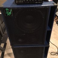
Ok. Yours will not be as complicated as the picture Slyjoe sent. That ads a switch for the mid range Lpad. It took me a while to see that they used the input jack dish for input speakons, the Lpad switch, and the horn attenuator. That's why there's so much going on up in that corner. Pretty slick! That's a great picture to use as a guide.
Looks like the +&- input on each circuit board are clearly marked on your gear. In the end, there will be + &- wires coming off each stage of the crossover and going to a driver. ( the wires to the horn will make a detour to the attenuator.)
In your box of gear, I don't see an input dish, or the input speakons, or a terminal strip. Not a big deal, you can fab up an input plate, out of scrap plywood, and mount your speakons. The horn attenuator can go anywhere you like, just make it easy to get to.
You want your input jacks to be recessed. I've used a hole saw to make a 3" hole, rounded over the edges with the router, then glued my scrap ply with the speakons mounted to the inside of the cab. You could expand on that to recess the horn control as well, or make another "dish".
You might also try to fit your three boards on the port shelf, and come up with a terminal strip.
I'll have to get into an old pc and look for some pictures. I'll check back in the morning.
Are you planning to solder or use crimp connectors?
I try to get the whole thing wired up and mounted on one piece of plywood that fits on the port shelf. Then I screw it securely to the shelf and make the last connections.